Surviving 1 second without battery power


Closed Thread
Results 1 to 28 of 28

Hybrid View

  1. #1
    Join Date
    May 2004
    Location
    NW France
    Posts
    3,653


    Did you find this post helpful? Yes | No

    Default

    Hi, Peu

    You're out ...

    Code:
    '@ device pic12f683,INTRC_OSC_NOCLKOUT , wdt_on, mclr_off, protect_off, bod_on
    
     @    __config _INTRC_OSC_NOCLKOUT & _PWRTE_ON & _WDT_ON &_BOD_ON & _MCLRE_OFF & _CP_OFF
     
     
    OSCCON = %01100110
    CMCON0 = %00000111     ' Disable comparator
    VRCON  = %00000000     ' disable
    ADCON0 = %11100000
    ANSEL  = %10000000
    
    '       I/Os
    gpio   = %00000000
    TRISIO = %00000000      ' no inputs 
    
    BOD var GPIO.0
    POR var GPIO.1
    
       
    IF PCON.1 = 0 and PCON.0 = 0 THEN BOD = 1	'BROWN OUT RESET BIT
    IF PCON.1 = 0 				 THEN POR = 1	'POWER ON RESET BIT
    
    PAUSE 1000
    
    GPIO = 0
    
    if PCON.1 = 1 AND PCON.0 = 0 then		'PCON.0 = BOD ;PCON.1 = POR
              
        GPIO.2 = 1         'GPIO.1 red led PIN6 shows a BOD state
        PAUSE 5000
        PCON.0 = 1
        gpio = %00000000
        
    endif
    
    PCON.1 = 1
    PCON.0 = 1
    
    While 1
    Wend
    
    END
    This works really fine, but with a 10 µ (MICRO) F ...and a 12F683

    so , some current draw improvements are still to add ...

    NOTE: All Outputs are Mosfet Buffered ( BS 170 ) ...

    Alain

    PS: You didn't use your brain too much, here ....
    Last edited by Acetronics2; - 13th March 2008 at 19:52.
    ************************************************** ***********************
    Why insist on using 32 Bits when you're not even able to deal with the first 8 ones ??? ehhhhhh ...
    ************************************************** ***********************
    IF there is the word "Problem" in your question ...
    certainly the answer is " RTFM " or " RTFDataSheet " !!!
    *****************************************

  2. #2


    Did you find this post helpful? Yes | No

    Default

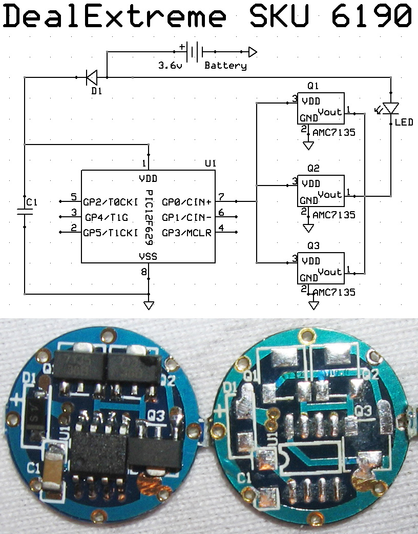
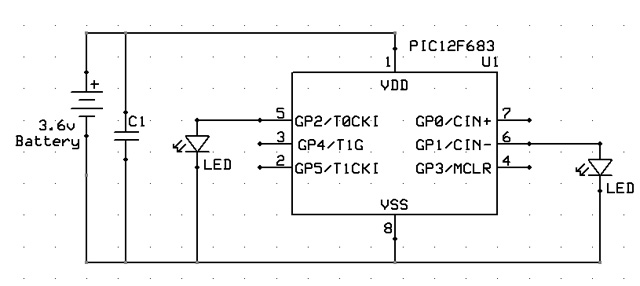
    Change your test circuit as follows:

    Put a diode between the cap and the battery disconnect point like the sample schematic at the beginning of this thread has. This will isolate the PIC power from the rest of the circuit so that the cap will power the PIC when the battery is disconnected.

    Connect the LED cathodes to the I/O pins. Then connect the LED anodes to the battery disconnect point between the battery and the diode that was added above. By doing this, the LEDs won't draw power once the battery is disconnected.
    Tim Barr

  3. #3
    Join Date
    Feb 2005
    Posts
    130


    Did you find this post helpful? Yes | No

    Default

    Quote Originally Posted by peu View Post
    [edit] Maybe I need to check for POR=1 and BOD=0 to know for sure that a BOD reset happened
    I wasn't that far with this late edit

    Quote Originally Posted by Acetronics View Post
    This works really fine, but with a 10 µ (MICRO) F ...and a 12F683

    so , some current draw improvements are still to add ...

    NOTE: All Outputs are Mosfet Buffered ( BS 170 ) ...

    Alain

    PS: You didn't use your brain too much, here ....
    What brain?

    Well I implemented your program and it worked, but the cap value was way too high, so I started lowering till I found a ridiculously low value...

    Then I examined your code, removed some chunks and commented it:

    Code:
    @ device pic12f683,INTRC_OSC_NOCLKOUT , wdt_on, mclr_off, protect_off, bod_on
    
    ' I use picbasic to compile!!
    
     '@    __config _INTRC_OSC_NOCLKOUT & _PWRTE_ON & _WDT_ON &_BOD_ON & _MCLRE_OFF & _CP_OFF
     
     
    OSCCON = %01100110
    CMCON0 = %00000111     ' Disable comparator
    VRCON  = %00000000     ' disable
    ADCON0 = %11100000
    ANSEL  = %10000000
    
    '       I/Os
    gpio   = %00000000
    TRISIO = %00000000      ' no inputs 
    
    ' SECTION? what is this section used for?
    ' BOD var GPIO.0
    ' POR var GPIO.1
    
       
    ' IF PCON.1 = 0 and PCON.0 = 0 THEN BOD = 1	'BROWN OUT RESET BIT
    ' IF PCON.1 = 0 THEN POR = 1	'POWER ON RESET BIT
    
    ' PAUSE 1000  this pause cannot be used in a flashlight environment
    '  SECTION?  what is this section used for?
    
    GPIO = 0
    
    if PCON.1 = 1 AND PCON.0 = 0 then		'PCON.0 = BOD ;PCON.1 = POR
              
        GPIO.2 = 1          'GPIO.2 green led PIN6 shows a BOD state
        PAUSE 1000          'I don't have patience :-)
        'PCON.0 = 1         ' not needed since you set this again below
        gpio = %00000000
        
    endif
    
    'PCON.1 = 1      replaced with one line :-)
    'PCON.0 = 1
    PCON=%00000011
    
    GPIO.1 = 1 'normal state red led
    While 1
    Wend
    
    END
    and if a picture is a 1000 words, we could say that a video is like 1000 pictures, so 1000x1000=1000000 words... WOW... I just wrote a book take a look at this video: http://www.veoh.com/videos/v6415763hQHpjMDy

    As you see, the cap is reaaally small, the green led shows BOD condition, and red led is normal operation. The diode you see there is not used. Also I left all the unused pins floating

    When I used large value capacitors, everytime I did a power interruption no matter if it was 1 second or 10 the BOD led turned on.

    I wonder why you had to use 10uF

    Also assembled a proto PCB using the 1st schematic to start testing a real world application.
    Last edited by peu; - 14th March 2008 at 00:15.

  4. #4
    Join Date
    May 2004
    Location
    NW France
    Posts
    3,653


    Did you find this post helpful? Yes | No

    Talking

    Quote Originally Posted by peu View Post
    I wasn't that far with this late edit

    What brain?


    .
    " Whose brain ??? " could have been good level humour ...

    Well I implemented your program and it worked, but the cap value was way too high, so I started lowering till I found a ridiculously low value...

    Then I examined your code, removed some chunks and commented it:


    << ' I use picbasic to compile!! >>

    Me too !!! ... did you notice a little difference between MPLAB and Microcode studio ???


    << I wonder why you had to use 10uF >>

    I don't know ... gives me a ~ .3 s power interrupt delay ... and it won't be my headache !!!
    The Pic itself draws .77 mA ...

    Regards
    Alain
    Last edited by Acetronics2; - 14th March 2008 at 15:28.
    ************************************************** ***********************
    Why insist on using 32 Bits when you're not even able to deal with the first 8 ones ??? ehhhhhh ...
    ************************************************** ***********************
    IF there is the word "Problem" in your question ...
    certainly the answer is " RTFM " or " RTFDataSheet " !!!
    *****************************************

  5. #5
    Join Date
    Feb 2005
    Posts
    130


    Did you find this post helpful? Yes | No

    Default

    Alain, I just sent you a Private Message.

    [edit] Sorry for the missunderstanding, and thanks for your reply
    Last edited by peu; - 14th March 2008 at 13:45.

Similar Threads

  1. Thermo 7 segments - little problem
    By fratello in forum mel PIC BASIC Pro
    Replies: 49
    Last Post: - 27th July 2013, 07:31
  2. RS485 bus - starting probem
    By wurm in forum mel PIC BASIC Pro
    Replies: 4
    Last Post: - 27th January 2010, 13:35
  3. 32 bit square root
    By Charles Linquis in forum mel PIC BASIC Pro
    Replies: 20
    Last Post: - 6th May 2009, 03:37
  4. one line led light make image
    By bioul in forum mel PIC BASIC Pro
    Replies: 7
    Last Post: - 13th February 2008, 12:19
  5. HSERIN doesn´t work
    By wurm in forum mel PIC BASIC Pro
    Replies: 4
    Last Post: - 29th July 2007, 14:23

Members who have read this thread : 0

You do not have permission to view the list of names.

Posting Permissions

  • You may not post new threads
  • You may not post replies
  • You may not post attachments
  • You may not edit your posts