Im reading different PIC datasheets so shed some light about the BOD sequence, but most of them share the same wording, Im really lost.
I made a little proggie to test what I've learned in this thread, but it does not work, maybe Im missing something stupid, but after many hours of trying, maybe what I need is a good rest:
Code:
@ device pic12f683,INTRC_OSC_NOCLKOUT , wdt_on, mclr_off, protect_off, bod_on

CMCON0 = %00000111     ' Disable comparator
VRCON  = %00000000     ' disable


'       I/Os
TRISIO = %00000000      ' no inputs

' definitions

BODD var PCON.0

gpio=%00000100            'I know program cold started
pause 1000                'gpio.2 green led pin5 indicates coldstart
gpio=%00000000

loop:

if BODD=0 then
    gpio=%00000010        'GPIO.1 red led PIN6 shows a BOD state
    pause 1000
    gpio=%00000000
    BODD=1
endif
goto loop
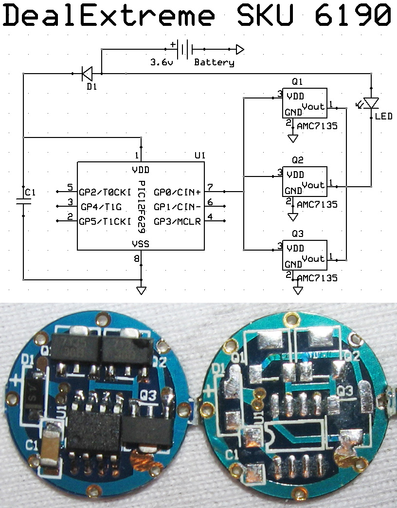
then the schematic is pretty simple, a ceramic capacitor at the power lines for storing some battery, a couple of leds at the specified pins and a momentary switch that allows me to cut VDD for a moment.
It does not vork 
[edit] Maybe I need to check for POR=1 and BOD=0 to know for sure that a BOD reset happened
Help! 


 (just crossed the 40 mark).
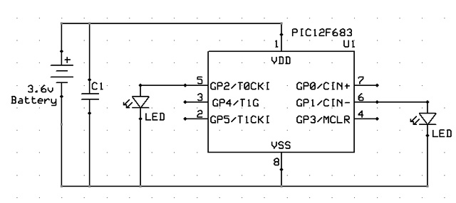


Bookmarks