Surviving 1 second without battery power


Closed Thread
Results 1 to 28 of 28

Hybrid View

  1. #1
    Join Date
    Feb 2005
    Posts
    130


    Did you find this post helpful? Yes | No

    Default

    I think I understand what you guys mean, this would be the metacode

    set BODEN config bit to 1

    set BOD bit to 1
    set POR bit to 1
    read level from eeprom / set level

    mainloop
    check for BOD/POR bits at PCON register
    if BOD=0 then wait for POR=0 and change to next level and write it to eeprom.
    goto mainloop
    end

    Is this correct?

    I have some questions:

    What would happen if power is lost while writing to eeprom?
    Can this be handled with PBP without using interrupts?

    Regarding the cap, I don't have a oscilloscope to see the discharge curve, it seems to last around 1seg to fall below 2v but this measurement was done by the eyemeter.

  2. #2
    Join Date
    May 2004
    Location
    NW France
    Posts
    3,653


    Did you find this post helpful? Yes | No

    Lightbulb

    Hi, Peu

    NO, you did not understand ...

    1) You enable BODEN, nothing else required ...

    2) AT program start, you first read the BOR bit

    3) If BOR Bit = 0 THEN (and only IF ) you increase the EEPROM content : That means power is back, and did not reach ZERO !!! ( no Pb to write , then ...)

    4) If BOR Bit = 1 power has gone to ZERO ( and BOR bit has been reset ) ... just read the EEPROM content .

    5) you SET BOR bit

    6) you run your "lighting" program ...

    Think simple !!!

    Alain
    Last edited by Acetronics2; - 12th March 2008 at 19:55. Reason: BOR Electrical levels inverted ...
    ************************************************** ***********************
    Why insist on using 32 Bits when you're not even able to deal with the first 8 ones ??? ehhhhhh ...
    ************************************************** ***********************
    IF there is the word "Problem" in your question ...
    certainly the answer is " RTFM " or " RTFDataSheet " !!!
    *****************************************

  3. #3
    Join Date
    Feb 2005
    Posts
    130


    Did you find this post helpful? Yes | No

    Default

    KISS principle... I know... Im getting older&rusty (just crossed the 40 mark).

    Will give your post explanation a try in real code and let you know. Thanks!

  4. #4
    Join Date
    Feb 2005
    Posts
    130


    Did you find this post helpful? Yes | No

    Default

    Quote Originally Posted by Acetronics View Post
    Hi, Peu

    NO, you did not understand ...

    1) You enable BODEN, nothing else required ...

    2) AT program start, you first read the BOR bit

    3) If BOR Bit = 1 THEN (and only IF ) you increase the EEPROM content : That means power is back, and did not reach ZERO !!! ( no Pb to write , then ...)

    4) If BOR Bit = 0 power has gone to ZERO ( and BOR bit has been cleared ) ... just read the EEPROM content .

    5) you run your "lighting" program ...

    Think simple !!!

    Alain
    Im kinda lost again:

    From TABLE 9-6: INITIALIZATION CONDITION FOR SPECIAL REGISTERS
    PCON is initialized with %00000010 (POR=1 BOD=0)
    From 2.2.2.6 PCON Register
    REGISTER 2-6: PCON — POWER CONTROL REGISTER (ADDRESS: 8Eh)

    bit 0 BOD: Brown-out Detect STATUS bit
    1 = No Brown-out Detect occurred
    0 = A Brown-out Detect occurred (must be set in software after a Brown-out Detect occurs)
    From these datasheet entries I dont understand when BOD goes to 1

  5. #5
    Join Date
    May 2004
    Location
    NW France
    Posts
    3,653


    Did you find this post helpful? Yes | No

    Talking

    Hi,

    Do not worry !!!

    1 = No Brown-out Detect occurred
    0 = A Brown-out Detect occurred (must be set in software after a Brown-out Detect occurs)

    sooo ... just use the Bit level corresponding to what happend ! ... invert BOR levels I indicated for 3) and 4) and you'll have it ...

    I've correct the thread , NOW ... I had not used that feature for a while ...

    << Im getting older&rusty (just crossed the 40 mark). >>

    ... and me the 51 Mark !!!

    Alain
    Last edited by Acetronics2; - 12th March 2008 at 19:56.
    ************************************************** ***********************
    Why insist on using 32 Bits when you're not even able to deal with the first 8 ones ??? ehhhhhh ...
    ************************************************** ***********************
    IF there is the word "Problem" in your question ...
    certainly the answer is " RTFM " or " RTFDataSheet " !!!
    *****************************************

  6. #6
    Join Date
    Feb 2005
    Posts
    130


    Did you find this post helpful? Yes | No

    Default

    Quote Originally Posted by Acetronics View Post
    Hi, Peu

    NO, you did not understand ...

    1) You enable BODEN, nothing else required ...

    2) AT program start, you first read the BOR bit

    3) If BOR Bit = 0 THEN (and only IF ) you increase the EEPROM content : That means power is back, and did not reach ZERO !!! ( no Pb to write , then ...)

    4) If BOR Bit = 1 power has gone to ZERO ( and BOR bit has been reset ) ... just read the EEPROM content .

    5) you SET BOR bit

    6) you run your "lighting" program ...

    Think simple !!!

    Alain
    I still have a doubt: when does the BOD bit goes from the initialization value ZERO (table 9-6) to ONE (No Brown-out Detect occurred) in a cold start scenario?

    At cold start the circuit should read the stored eeprom value not write a new one


  7. #7
    Join Date
    Feb 2005
    Posts
    130


    Did you find this post helpful? Yes | No

    Default

    Im reading different PIC datasheets so shed some light about the BOD sequence, but most of them share the same wording, Im really lost.

    I made a little proggie to test what I've learned in this thread, but it does not work, maybe Im missing something stupid, but after many hours of trying, maybe what I need is a good rest:

    Code:
    @ device pic12f683,INTRC_OSC_NOCLKOUT , wdt_on, mclr_off, protect_off, bod_on
    
    CMCON0 = %00000111     ' Disable comparator
    VRCON  = %00000000     ' disable
    
    
    '       I/Os
    TRISIO = %00000000      ' no inputs      
    
    ' definitions
               
    BODD var PCON.0
    
    gpio=%00000100            'I know program cold started
    pause 1000                'gpio.2 green led pin5 indicates coldstart
    gpio=%00000000   
    
    loop:
    
    if BODD=0 then           
        gpio=%00000010        'GPIO.1 red led PIN6 shows a BOD state
        pause 1000
        gpio=%00000000
        BODD=1
    endif
    goto loop
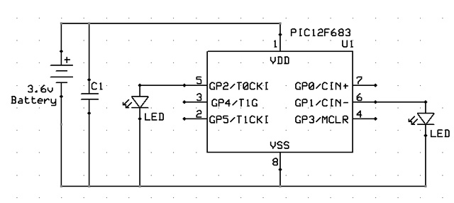
    then the schematic is pretty simple, a ceramic capacitor at the power lines for storing some battery, a couple of leds at the specified pins and a momentary switch that allows me to cut VDD for a moment.

    It does not vork

    [edit] Maybe I need to check for POR=1 and BOD=0 to know for sure that a BOD reset happened

    Help!
    Last edited by peu; - 13th March 2008 at 01:11.

  8. #8
    Join Date
    May 2004
    Location
    NW France
    Posts
    3,653


    Did you find this post helpful? Yes | No

    Thumbs down

    gpio=%00000010 'GPIO.1 red led PIN6 shows a BOD state
    pause 1000


    Here is the best reason ( may be others ... I must check ) for your gadget not to work ...

    THE DEVICE MUST DRAW AS LITTLE CURRENT AS POSSIBLE !!!

    Your led leads VCC voltage to ZERO ... so ... POR and not BOR !!!

    Alain
    ************************************************** ***********************
    Why insist on using 32 Bits when you're not even able to deal with the first 8 ones ??? ehhhhhh ...
    ************************************************** ***********************
    IF there is the word "Problem" in your question ...
    certainly the answer is " RTFM " or " RTFDataSheet " !!!
    *****************************************

  9. #9
    Join Date
    Feb 2005
    Posts
    130


    Did you find this post helpful? Yes | No

    Default

    Rest helped clear my mind

    I will test this code as soon I arrive at my office:

    Code:
    @ device pic12f683,INTRC_OSC_NOCLKOUT , wdt_on, mclr_off, protect_off, bod_on
    
    CMCON0 = %00000111     ' Disable comparator
    VRCON  = %00000000     ' disable
    
    
    '       I/Os
    TRISIO = %00000000      ' no inputs      
    
    ' definitions
     
    ' init values
    
    if PCON.0=0 then
      gpio=%00000100            'Brown-out detected turn on LED on PIN5
    else
      gpio=%00000010            'Brown-out NOT detected turn on LED on PIN6
    endif
    
    'main loop
    
    loop:
    goto loop
    I can't imagine simpler code to test the BOD function. Do you see something wrong?

  10. #10
    Join Date
    May 2004
    Location
    NW France
    Posts
    3,653


    Did you find this post helpful? Yes | No

    Lightbulb

    Hi,

    Was not so easy ... but finally got it !!!

    all the trick is in the bits setting and testing scheduling ... Always keep in mind the processor will re-start from the beginning.

    Have fun ... the ( let's be modest ! ... A ) working listing waits for your first try ...

    Other trick : May be you'll have to test greater values capacitors ...

    Alain
    ************************************************** ***********************
    Why insist on using 32 Bits when you're not even able to deal with the first 8 ones ??? ehhhhhh ...
    ************************************************** ***********************
    IF there is the word "Problem" in your question ...
    certainly the answer is " RTFM " or " RTFDataSheet " !!!
    *****************************************

Similar Threads

  1. Thermo 7 segments - little problem
    By fratello in forum mel PIC BASIC Pro
    Replies: 49
    Last Post: - 27th July 2013, 07:31
  2. RS485 bus - starting probem
    By wurm in forum mel PIC BASIC Pro
    Replies: 4
    Last Post: - 27th January 2010, 13:35
  3. 32 bit square root
    By Charles Linquis in forum mel PIC BASIC Pro
    Replies: 20
    Last Post: - 6th May 2009, 03:37
  4. one line led light make image
    By bioul in forum mel PIC BASIC Pro
    Replies: 7
    Last Post: - 13th February 2008, 12:19
  5. HSERIN doesn´t work
    By wurm in forum mel PIC BASIC Pro
    Replies: 4
    Last Post: - 29th July 2007, 14:23

Members who have read this thread : 0

You do not have permission to view the list of names.

Posting Permissions

  • You may not post new threads
  • You may not post replies
  • You may not post attachments
  • You may not edit your posts