

YesOriginally Posted by richard

VSS


Yes
VSS
My Creality Ender 3 S1 Plus is a giant paperweight that can't even be used as a boat anchor, cause I'd be fined for polluting our waterways with electronic devices.
Not as dumb as yesterday, but stupider than tomorrow!

i would start with a 100R resister between each cathode and vss , if the backlight is not brite enough
drop the R incrementally .
Warning I'm not a teacher
you should have specs on max current for the backlight, the actual R used should limit to that value or less at 100% pwm modulation at 5v. imo
Warning I'm not a teacher
Roger, Richard.
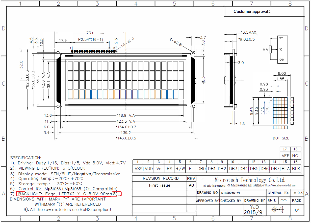
Specs say 90mA. Gonna have to test to see if that's into the "overbright" range with pixels bleeding through.
I remember setting this "by eye" at an intensity that was "aesthetically pleasing". I was also trying to save on AMPS too since I was initially thinking of running off USB power.
My Creality Ender 3 S1 Plus is a giant paperweight that can't even be used as a boat anchor, cause I'd be fined for polluting our waterways with electronic devices.
Not as dumb as yesterday, but stupider than tomorrow!

The 2N2907 is a PNP transistor while IRF530P is a N-Channel FET. So the circuit should be different.
In the case of 2N2907 you source current to the LCD but with IRF you should sink current to the ground.
And of course the polarity of the control signal should be inverted for the IRF. Hope you are aware of that.
As for the noise, your circuit does not have any decoupling capacitors very close to your switching transistor (either 2N or IRF) and to the ground. Put a 100nF and a 10uF in parallel and I am sure things will be better.
Also ground loops etc will have massive effect on this. Do not trust breadbording for this. Noise will be much more on such circuits even with capacitors.
Ioannis
IRF5305P is P channel.
https://www.mouser.ca/ProductDetail/...uFut1Niv57Vgi1
My Creality Ender 3 S1 Plus is a giant paperweight that can't even be used as a boat anchor, cause I'd be fined for polluting our waterways with electronic devices.
Not as dumb as yesterday, but stupider than tomorrow!
I could be wrong but the way I read your instruction sheet I see this..... think the module has the dimmer mechanism internal and is controlled by 0-5 volt on the Vo pin
-
-

Yeah, as I corrected myself in post #38,
https://www.picbasic.co.uk/forum/sho...583#post156583
it's the backlight that I'm controlling.
This is white-on-black LCDs. I've set V0 to a "visually acceptable level" (still have to test Richard's suggestion), and I control the brightness of the LCDs only with the backlight.
My Creality Ender 3 S1 Plus is a giant paperweight that can't even be used as a boat anchor, cause I'd be fined for polluting our waterways with electronic devices.
Not as dumb as yesterday, but stupider than tomorrow!
Obviously I mistyped the part number. Yes it is a P channel.
From the datasheet the Vth seems to be 4Volts min. Have you tested yet this MosFet?
Please check with an Osciloscope that the MosFet is fully closed at PIC low state, so that there is no voltage drop on S-D pins.
Was there a specific reason that you selected a P channel instead of a N channel control of the PWM signal? Usually the N channel have better characteristics in terms of Rds.
Ioannis
Nope. But I'm using a IRFZ44N n-channel to PWM the LED strip with has similar specs.
Good idea. Choosing the proper resistors to drive the MOSFET is still a black art to me.
Because when I first started testing blue-on-white LCDs, I was PWMing both the Contrast (V0) and Backlight (LedA). I didn't even consider MOSFETs and went straight to transistors since we're not talking about a lot of current. Why I chose PNP transistors back then is a mystery; maybe I saw a schematic on google and copied that.
I've since switched to white-on-black LCDs, I don't need to have adjustable Contrast (V0). So controlling the Backlight with a PNP transistor is just "the old way of doing things". But since noise has become an issue, getting a P-channel MOSFET seemed like the logical way to replace the PNP.
But if I had thought about it for 2 seconds, I would have realized I have access to both the Anode and Cathode on the Backlight. Since I already have an IRFZ44N on the circuit, it would cost less at JLCPCB to use another IRFZ44N instead of a second type of component.
So that's the long-winded way of me saying that now I'm going to swap the 2N2907A PNP to a IRFZ44N n-channel.
Funny story, I finally realized the letter at the end of a MOSFET seems to indicate the channel. I don't know if it holds true for all, but it's working for the first two that I researched.

My Creality Ender 3 S1 Plus is a giant paperweight that can't even be used as a boat anchor, cause I'd be fined for polluting our waterways with electronic devices.
Not as dumb as yesterday, but stupider than tomorrow!
Switching to MosFet from bipolar, as Richard noted, it will introduce MORE noise because they are faster.
So, do add capacitors (100nF plus 10uF) as close as possible to the Mosfet power supply, taking care of ground loops at the same time.
Ioannis
a waste of time until he address' the correct current limiting resistors for each displaySo, do add capacitors
if its really 90mA per display then a 1000uF might help a little.
The peak current as it stands could be very high depending on led vf , could be amps , who knows
Warning I'm not a teacher
OK, but having a 4.000uF on the 5V rail is too much, isn't it?
Ioannis
You seem to be moving the goal posts. One 1000uF at the pnp tranny emitter since all four back lights are parallel driven from that source
Warning I'm not a teacher
By "if its really 90mA per display then a 1000uF might help a little" seemed to me that you meant 1000uF per display.
In any case though, the 1084 or even the humble 7805, do not have any problem with large capacitance.
I bet a reverse biased diode, across output/input pin, would be needed to protect the regulator, in case the Reg. input is grounded for whatever reason while the outuput cap is still charged.
Ioannis
Yup, I saw that in the datasheet.
Haven't done any of the suggestions for the LCDs yet. I'm doing voltage regulator heat tests for now; looking for the best heatsink setup.
This is how I'm running the LM1084-ADJ now:
Black is from the datasheet, red is my adjustments.
Last edited by Demon; - 16th November 2024 at 01:43.
My Creality Ender 3 S1 Plus is a giant paperweight that can't even be used as a boat anchor, cause I'd be fined for polluting our waterways with electronic devices.
Not as dumb as yesterday, but stupider than tomorrow!
if you solve the backlight issue then you will most likely find the wall warts simple smps are not the problem and the regs and heatsinks are unnecessaryHaven't done any of the suggestions for the LCDs yet. I'm doing voltage regulator heat tests for now; looking for the best heatsink setup.
Warning I'm not a teacher
The LCD datasheets note that the backlight is 5v at 90mA, isn't it?
So I understand that no current liminting resistor is necessary, as it is included on the LCD board.
Ioannis
you may be correct but that does not explain why the backlights cause so much noise.So I understand that no current liminting resistor is necessary, as it is included on the LCD board
it would be a 2 minute job to apply 5v to the backlight and measure the current .[i would used a cc regulated ps just in case]
i have never come across an lcd of that type with anything onboard to limit led current.
Warning I'm not a teacher
Well, there are not many but they exist. I use them all the time to avoid external resistors.
If the datasheet marks it as 5V then the LCD includes the limiting resistor. Otherwise they note 4 or 4.2 volts at specific current and specific resistor for 5V supply.
Ioannis
I've put on hold debugging/testing LCDs, ADC and whatnot until I get a handle on power regulation.
Thanks to Ioannis, the datasheet for the TPS voltage regulators led me to TI's WEBBENCH; that tool is just remarkable for the newb like me. I've spent the last 2 days playing with various ICs, checking their availability on JLCPCB and such.
The 2 best features has to be that Alternate and Simulate features; you can chose equivalent parts that are no available at JLCPCB, and see exactly what the output ripple will look like.
I've narrowed down my choice to a TPS56637. I can run 5V @ 5A using 7V to 12V at 11.4mV Vout Peak-Peak; it can do more, but the output ripple degrades as you push it.
This is awesome because it gives me a wider range of power supply adapters. I was initially fixated on running on 9V to limit heat from conventional voltage regulators.
The datasheet even gives a very detailed PCB layout:
Thanks mucho Ioannis!
My Creality Ender 3 S1 Plus is a giant paperweight that can't even be used as a boat anchor, cause I'd be fined for polluting our waterways with electronic devices.
Not as dumb as yesterday, but stupider than tomorrow!
You are most welcome! Thats what friends are for, right?
The selected TPS is difficult to handle by hand. Needs heatsinking on the PCB by special design. I do understand why you selected this one over the TPS565208, that is super easy to handle.
Amazing chips TI has...!
Ioannis
Definitely, that's why I did my best to mimic the "suggested" layout I posted above. I figure there's countless hours or even days put into that design.
I came up with this 4-layer PCB, top layer:
Both inner layers are identical:
And the bottom layer:
I did my best to use the same outlines, but I didn't have identical sized components, so I had to make due.
- Rpg goes to VCC on the datasheet drawing, but goes straight to 5Vout on the generated schematic.
- they have a single Cin cap, but mine is split into 2 using alternate parts.
- my inductor seems to be twice as large as theirs.
Also, the Webench schematic for 7-12Vin to 5A-5Vout didn't have these resistors:
- Rmode
- Renb
- Rent
So I don't have that trace from PGND going up to VIN.
The last thing I have to adjust is the copper layers; I remember reading something about needing 2 ounces top and bottom, and 1 ounce inners (or something like that - got reading to do).
Looks like this in 3D:

Last edited by Demon; - 25th November 2024 at 22:30.
My Creality Ender 3 S1 Plus is a giant paperweight that can't even be used as a boat anchor, cause I'd be fined for polluting our waterways with electronic devices.
Not as dumb as yesterday, but stupider than tomorrow!
ARGH! Of course it's only now that I notice Webench generated a layout specifically for that schematic.
I couldn't find any mention of copper thickness in the datasheet. No mention in the Evaluation Board for the TPS56637, but it does have a much nicer layout with A LOT MORE cooling holes and a wider area.
I must have read about the copper thickness in the datasheet for another TPS. I just can't remember which cause I looked at so many.
EDIT: No mention of copper in their Quick Reference Guide:
https://www.ti.com/lit/an/slva958b/slva958b.pdf
Last edited by Demon; - 25th November 2024 at 23:13.
My Creality Ender 3 S1 Plus is a giant paperweight that can't even be used as a boat anchor, cause I'd be fined for polluting our waterways with electronic devices.
Not as dumb as yesterday, but stupider than tomorrow!
Bingo, I must have seen this while researching the LM1084. Digikey PDF for the LM76002 on page 43:
https://www.digikey.ca/en/htmldatash.../1/lm76003rnpt
TI recommends using a four-layer board with the copper thickness, for the four layers, starting from the top one, 2 oz / 1 oz / 1 oz / 2 oz.
My Creality Ender 3 S1 Plus is a giant paperweight that can't even be used as a boat anchor, cause I'd be fined for polluting our waterways with electronic devices.
Not as dumb as yesterday, but stupider than tomorrow!
TI's Eval board for the TPS56637 is 51mm x 64mm. I figure it would be wise for me to use the same dimensions until I have an actual board to check under the infra-red camera.
Increased the amount of cooling VIAs like on the Eval board.
Used a DIP header for the leads for a cleaner look once on the prototype.
Increased thicknesses to 2-1-1-2 ounces and tweaked the trace width/space according to JLCPCB minimum requirements for a 2oz board.
I still have to figure out how I can make my VIAs have large copper rings like the Eval board. I probably have to replace them with actual holes (like I have on the 4 corners - nice visible copper ring).
My Creality Ender 3 S1 Plus is a giant paperweight that can't even be used as a boat anchor, cause I'd be fined for polluting our waterways with electronic devices.
Not as dumb as yesterday, but stupider than tomorrow!
Had to make the hole a Part, not included in Schematic, BOM or To Be Populated.
Discovered the Create From Selection / Create Array feature; real time saver to make grids of parts.
Starting to look 1/2 decent.
My Creality Ender 3 S1 Plus is a giant paperweight that can't even be used as a boat anchor, cause I'd be fined for polluting our waterways with electronic devices.
Not as dumb as yesterday, but stupider than tomorrow!
Wow! You did a lot of work!
I am pretty sure that the extra layers TI suggest are for less noise ad better heat dissipation. Have you checked how much extra cost is added by JLCPCB?
In general if you want/need to make the board smaller, you can move all componets to the left, connector closer to the inductor and the right board edge also moved to the left. I don't see why this pcb needs to be that large. Saves cost also I guess.
I'd add an extra output capacitor for less noise and better operation without much cost. Parallel capacitors make for lower ESR also.
Nice design. You become an KiCad expert!
Ioannis
Last edited by Ioannis; - 26th November 2024 at 07:22.
EDIT:
At first I was tempted to make 2 prototypes; 2 layers and 4 layers; just to see if the extra cost is worth it. But the more I think about it, the more I'm leaning for the 4-layer design.
Two of the main objectives with this circuit is to reduce heat and stabilize the voltage (ripples). If the pros design their Eval board to that size with 4 layers, I can't really see why I should consider cutting corners.
But boy am I tempted.
Last edited by Demon; - 26th November 2024 at 23:08.
My Creality Ender 3 S1 Plus is a giant paperweight that can't even be used as a boat anchor, cause I'd be fined for polluting our waterways with electronic devices.
Not as dumb as yesterday, but stupider than tomorrow!
Not yet, I wanted to get as close to a "finalized design" before using JLCPCB's quote generator.
I didn't know that about the lower ESR.
EDIT the CAPS section
I just noticed the datasheet has a range of output capacitance at 5V from 25 to 100uF (table 4). So I just added 10uF and 1uF ceramics alongside the 47uF.
These guys have a nice bla-bla about "why there can be too much output capacitance on SMPS circuits":
https://www.cui.com/blog/understandi...citance-limits
Thanks, but I can't really take credit for the design. I feel like Mr. Bean copying the test answers from the guy next to him. I really did put a lot of effort to do as close to what TI recommends.
As for "Kicad expert", that remains to be seen.
Last edited by Demon; - 27th November 2024 at 17:23.
My Creality Ender 3 S1 Plus is a giant paperweight that can't even be used as a boat anchor, cause I'd be fined for polluting our waterways with electronic devices.
Not as dumb as yesterday, but stupider than tomorrow!
Well, if I'm going to have all that unused real-estate at the top, might as well do something with it:
- DC jack,
- power switch,
- multiple output headers,
- amp and volt test points.
It's all parts I have on hand, so it's not really costing me more. I don't see how it would disturb the cooling, since TI placed all the ventilation holes on the bottom section. It anything, it's extra cooling fins.
Now I just have to remember to slap a jumper on the amp test point for the circuit to work.
My Creality Ender 3 S1 Plus is a giant paperweight that can't even be used as a boat anchor, cause I'd be fined for polluting our waterways with electronic devices.
Not as dumb as yesterday, but stupider than tomorrow!
4 layers with 2-1-1-2 ounces with assembly, the area of my circuit jumps from 63mm x 50mm up to 73mm x 70mm.
2oz $32.20
1oz $16.07
Another issue, I can't use Economy with 0201 SMD, i have to use Standard. I had to swap 0201 resistor and capacitor for 0402.
Final bill for 5 PCBs:
- PCB $55.45
- Assembly $83.89
- Total $165.21 (with UPS shipping), $33.04 each PCB.
Plan B:
1oz all layers
PCB $23.15
PCBA $67.92
Ship $ 25.87
Total $116.94, $23.39 each PCB.
Tempted to go with plan B. It's not like I'm going to push 5 amps, most likely 2.5A at best.
My Creality Ender 3 S1 Plus is a giant paperweight that can't even be used as a boat anchor, cause I'd be fined for polluting our waterways with electronic devices.
Not as dumb as yesterday, but stupider than tomorrow!
Ten dollars is quite enough. I'd select that 1oz too.
Maybe and more caps too.
Ioannis
I ordered 2 models:
- 4 layers, all 1 oz, 5 for $147 including shipping and duties, $29.40 each
- 2 layers, all 1 oz, 5 for $108 including shipping and duties, $21.60 each
I was able to stay on Economic price by avoiding 2oz layers, and remained at recommended area size by TI.
Output caps, 47uF (recommended), 10uF and 1uF.
I was tempted to add 0.1uF and 0.001uF but I thought I might be exaggerating. I can still add them in the final version if you guys think I should; I have room and it's not like they cost anything.
At least I'll have something to see how it ripples using PWM from transistors and mosfets.
I can also push it for heat test by PWMing a whole roll of LED strip.
Last edited by Demon; - 30th November 2024 at 22:45.
My Creality Ender 3 S1 Plus is a giant paperweight that can't even be used as a boat anchor, cause I'd be fined for polluting our waterways with electronic devices.
Not as dumb as yesterday, but stupider than tomorrow!
I can get the price down a bit more by using another inductor:
Current: XAL1010-332MED by Coilcraft, $4.4191 x 5 = $22.10
Alternative: SRP1265A-3R3M by Bourns, $1.5387 x 5 = $7.70
That's a difference of $14.40 ($2.88/unit)
I didn't use the Bourns cause I'd have to order a minimum of 10 from Mouser, and that takes 8-15 lead days, and I wanted my PCB for testing yesterday.
There was 73 inductors in stock from Coilcraft, but that's already down to 38 (I only used 10 in my 2 orders).
Ioannis, have you had any experience ordering from Element or Onlinecomponents?
My Creality Ender 3 S1 Plus is a giant paperweight that can't even be used as a boat anchor, cause I'd be fined for polluting our waterways with electronic devices.
Not as dumb as yesterday, but stupider than tomorrow!
Once I get my order and done some testing, I'll be in a better position to know what configuration of layers I'm going to need.
I'm always getting emails from PCB assembly suppliers from alibaba, so I'll to make a RFQ for that "winning" configuration.
Just to see if I can get anything better than JLCPCB.
That'll also give me a chance to find a good competitor for my PCBs in the future. But I gotta admit, JLCPCB's online system is pretty slick once you get used to it.
My Creality Ender 3 S1 Plus is a giant paperweight that can't even be used as a boat anchor, cause I'd be fined for polluting our waterways with electronic devices.
Not as dumb as yesterday, but stupider than tomorrow!
No. My country adds a lot of import taxes so I select suppliers within European Union or Mouser that ships tax free.
May main suppliers are Mouser, TME, SOSelectronics and local resellers for larger quantities.
Regarding the inductors, I think either Coilcraft or Burns (or other reputable brands) will make no difference, as long as you select one that has the specs.
At testing time you will see if adding more caps on output of the power supply makes any significant difference. Can't tell right now.
For mass production of assembled pcb JLCPCB may be more expensive. I usually do this for no more than 20-30 pcs, depending on the component count too. Greater production is cheaper for me if I do it locally and just order only the pcb's from JLCPCB.
Ioannis
Assembled, checked each header and basic test on v1; 2 layer, 1-1oz.
Now I need to finish my load tester using this puppy.
The plan is to PWM the power resistor while monitoring current, and using E02 thermal camera to watch heat spots on PCB.
Still undecided if using N or P channel logic-level MOSFET. I have yet to find a good tutorial to determine the base resistor.
My Creality Ender 3 S1 Plus is a giant paperweight that can't even be used as a boat anchor, cause I'd be fined for polluting our waterways with electronic devices.
Not as dumb as yesterday, but stupider than tomorrow!
Tested on prototype board; 430mA.
Top side, TPS56637 step-down IC is the hottest at 25C, followed by inductor and switch bracket. I just touched power jack at far left, so that's not actual temp.
Bottom side, center is at 23C, the max spots are my finger (can see through top left mounting hole too) and LED strip in background.
That's insane compared to 7805 or LM1084. Humungous difference in efficiency and heat (never expected it to be so much difference).
I can touch this with my fingers.
Last edited by Demon; - 6th December 2024 at 23:40.
My Creality Ender 3 S1 Plus is a giant paperweight that can't even be used as a boat anchor, cause I'd be fined for polluting our waterways with electronic devices.
Not as dumb as yesterday, but stupider than tomorrow!
The LM1084 was maxxing out near 124C, and that was only at 300mA with heatsinks on front and back.
I'm both flabber and gasted.
My Creality Ender 3 S1 Plus is a giant paperweight that can't even be used as a boat anchor, cause I'd be fined for polluting our waterways with electronic devices.
Not as dumb as yesterday, but stupider than tomorrow!
 Members who have read this thread : 0
You do not have permission to view the list of names.
 Posting Permissions

Bookmarks