

What kind of terminal are you using?
Can you post your wiring ?
Al.


What kind of terminal are you using?
Can you post your wiring ?
Al.
All progress began with an idea
Well it looks like i found the probleme, i looked over the max232 data sheet and i frogot to connect vcc and gndOriginally Posted by aratti


Now i recive the expected output but it wont read the input.
Any ideas?Code:DEFINE OSC 4 'intcon=0 ' Interrupts disabled cm1con0=0 ' Comparator 1 disabled cm2con0=0 ' Comparator 2 disabled 'cm2con1=0 ' Comparator 2 disabled ANSEL=0 ' Pins to be Digital ANSELH=0 ' Pins to be Digital Include "modedefs.bas" DEFINE HSER_RCSTA 90h DEFINE HSER_TXSTA 24h 'sets bergh = 1 or 20h sets = 0 'define HSER_BAUDCON 0h ' 0h 'DEFINE HSER_BAUD 9600 '16468 DEFINE HSER_SPBRG 25 DEFINE HSER_CLROERR 1 rxVal Var Byte HSEROUT ["Waitin signal"] main: hserin [rxVal] hserout [rxVal] 'HSEROUT ["Test should work"] pause 20 goto main
And Thx for the help so far, sorry for not checking the schematics better
and im using 232analyzer terminal software
Last edited by krise86; - 18th April 2010 at 21:16.
Can you post the schematic?
Al.
All progress began with an idea
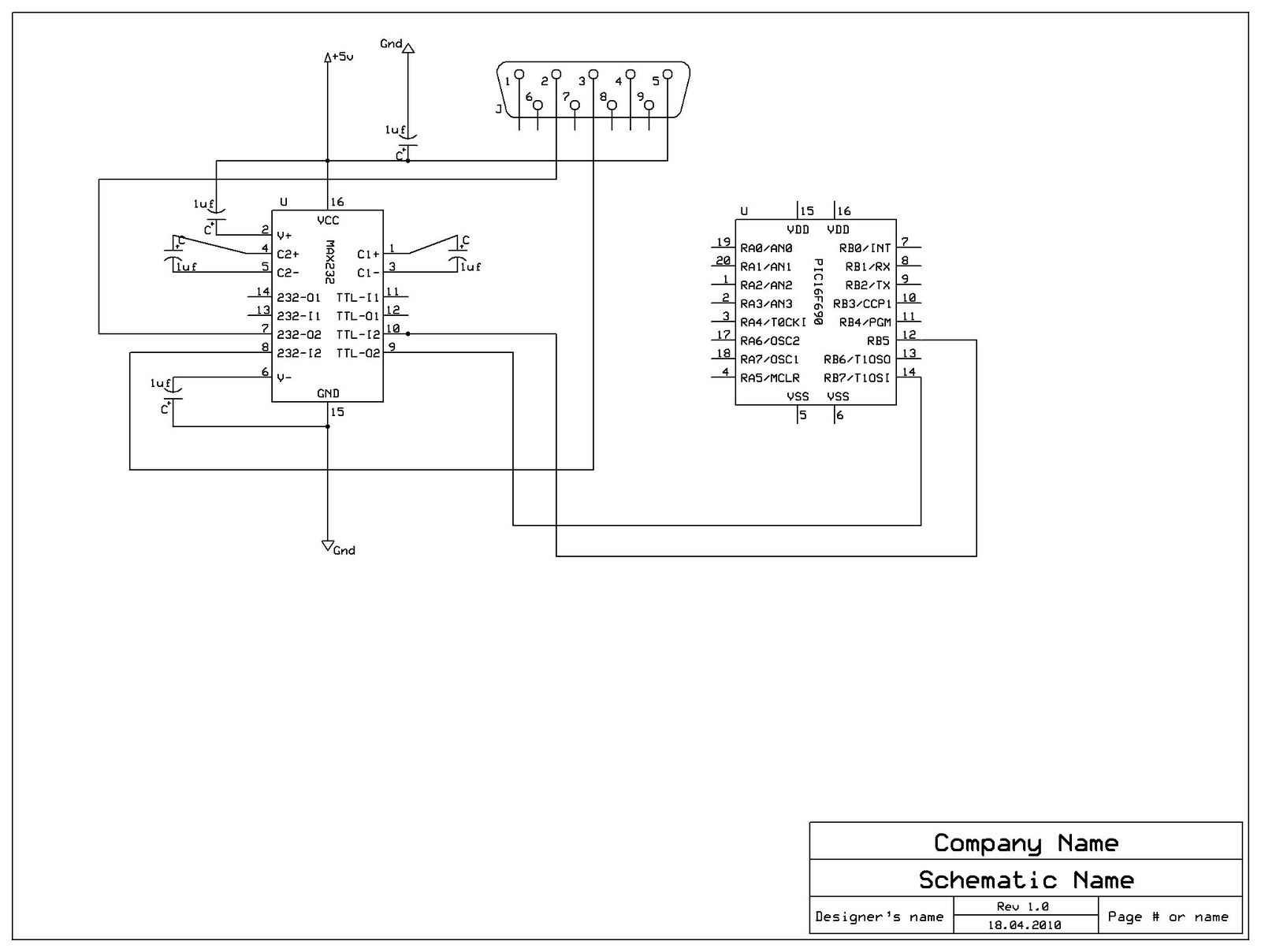
Something doesn't work with your wiring:
Max232 pin 10 should be connected to pic 16F690 pin 10 (RB7 Tx)
Max232 pin 9 should be connected to pic 16F690 pin 12 (RB5 Rx)
Connect a decoupling capacitor 10nF from Vdd to Vss on pic power pins.
Al.
All progress began with an idea
Well it is connected that way pin 10 -> rb7 and pin9 -> rb5
The 16f690 was not in the schematics program but that how i connected it.
but im reading -10v on rs232 pin 3 and 5 is that right?
I dont have a 0,01uf can i use 0,1uf?
wait i think it's on the demo board
Yes! Max232 is a voltage level translator.but im reading -10v on rs232 pin 3 and 5 is that right?
Yes!I dont have a 0,01uf can i use 0,1uf?
Al.
Last edited by aratti; - 18th April 2010 at 23:24.
All progress began with an idea
 Members who have read this thread : 0
You do not have permission to view the list of names.
 Posting Permissions
Bookmarks