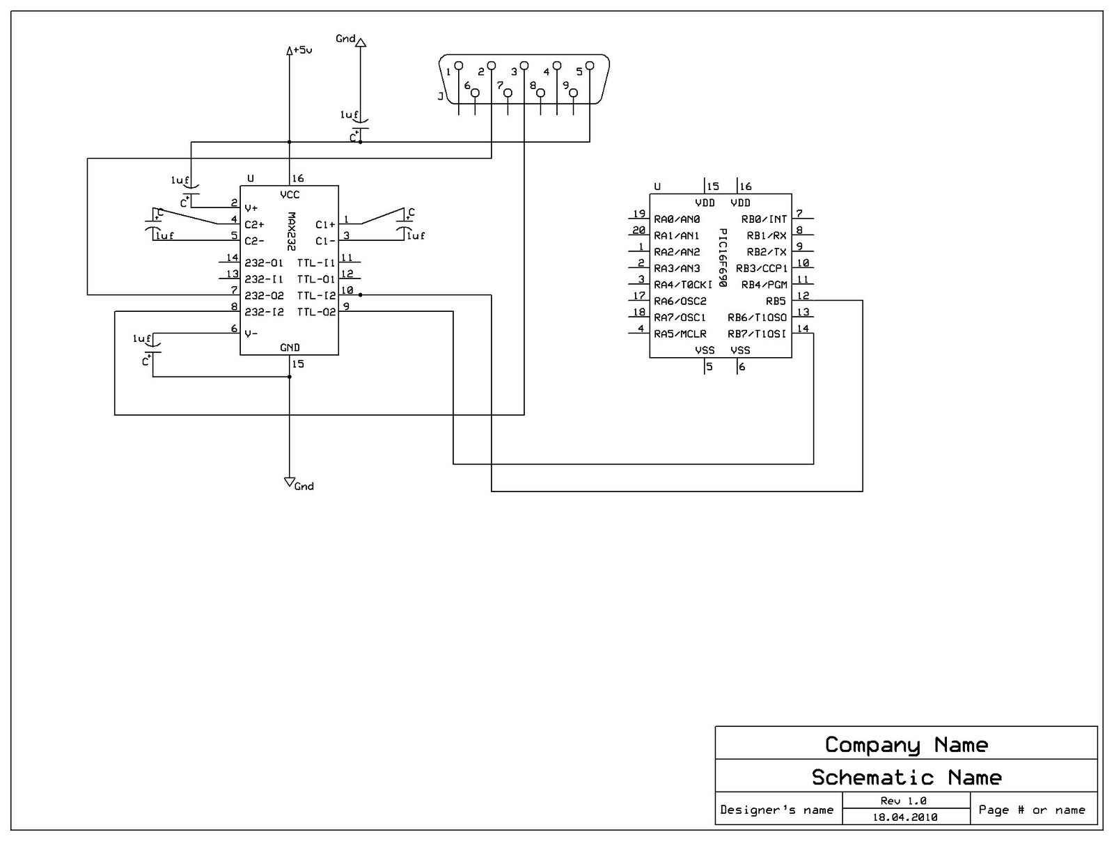
Something doesn't work with your wiring:
Max232 pin 10 should be connected to pic 16F690 pin 10 (RB7 Tx)
Max232 pin 9 should be connected to pic 16F690 pin 12 (RB5 Rx)
Connect a decoupling capacitor 10nF from Vdd to Vss on pic power pins.
Al.
All progress began with an idea
Well it is connected that way pin 10 -> rb7 and pin9 -> rb5
The 16f690 was not in the schematics program but that how i connected it.
but im reading -10v on rs232 pin 3 and 5 is that right?
I dont have a 0,01uf can i use 0,1uf?
wait i think it's on the demo board
Yes! Max232 is a voltage level translator.but im reading -10v on rs232 pin 3 and 5 is that right?
Yes!I dont have a 0,01uf can i use 0,1uf?
Al.
Last edited by aratti; - 18th April 2010 at 23:24.
All progress began with an idea
Yes place a led with 1K in series from pin 9 to gnd.That did nothing, is there a way to check if the signal is coming out from pin 9 on max232?
But, I am more interested on how many IO pins you are using. Now If you have inputs pins floating (not connected) this can produce wierd result.
I noted in your code, that you are not setting the tris registers, please do it. Set all non used pins as output and place them to a logic zero.
Example (I assume you are using only the serial pins) :
TrisA = %00000000
PortA = 0
TrisB = %00100000 ' if the only input is pin 10 Rx
PortB = 0
TrisC = %00000000 ' if none of the portC pins are used
PortC = 0
The above code has to be written on top of your code. It will set all non used port as outputs @ logic zero, avoiding to leave inputs floating.
If your arrangement is different modify the tris command to suite your need.
Al.
Last edited by aratti; - 18th April 2010 at 23:50.
All progress began with an idea
Bookmarks