

its alive i think
gives me a 63 rpm


its alive i think
gives me a 63 rpm
Warning I'm not a teacher

Richard,
looking at your code,i'm learning lots of things.
All the registers you have are constants. And that is what i've thought also in the beggining.
But in the manual it says that we never use constants for the I2C command.Code:;----------------------- REGISTER ------------------------- REG_TEMP_INT con $1F REG_TEMP_FRAC con $20 REG_TEMP_CONFIG con $21 REG_PART_REVISION con $FE REG_MODE con $09 REG_SPO2_CONFIG con $0A ;SPO2_ADC_RGE[6:5]SPO2_SR[4:2]LED_PW[1:0] REG_LED1_PA con $0C REG_LED2_PA con $0D FIFO_WR_PTR con $04 ;FIFO_WR_PTR[4:0] FIFO_RD_PTR con $06 FIFO_DATA con $07 FIFO_CONFIG con $08 ;FIFO_A_FULL[3:0] SMP_AVE[7:5] STATUS1 con 0 ;A_FULL[7] ' -----------------------------------------------------------------------------|
What i have realised is that you refer to the
everytime you need to asign a constant value to it. Is that right? with that way we alter the restriction of using constants. (or am i wrong?)Code:reg var byte
Sencod question.
I see you are always using the Write Address:
even if you want to read from:Code:ADDR = $ae ; addr is 0x57 << 1 reg = REG_PART_REVISION i2cread SDA,scl,ADDR,reg,[REVISION,PARTID] reg = REG_MODE i2cwrite SDA,scl,ADDR,reg,[3] reg = REG_SPO2_CONFIG i2cwrite SDA,scl,ADDR,reg,[$20] reg = REG_LED2_PA i2cwrite SDA,scl,ADDR,reg,[9] reg = REG_LED1_PA i2cwrite SDA,scl,ADDR,reg,[9] reg = FIFO_CONFIG i2cwrite SDA,scl,ADDR,reg,[16]
im confused here. When do we use the write address and when do we use the read address!!!Code:reg= REG_TEMP_INT i2cread sda,scl,ADDR,reg,[fifo[0],fifo[1]]
wow, ok little by little because i need to undestand what you have done.Originally Posted by richard

apart from that 63 bpm is quite ok and looks healthy.
Low pass filter in excel
makes peak detection look possible
Code:'****************************************************************'* Name : MAX30102 FOR PIC 18 DEMO * '* Author : Richard * '* Notice : * '* : * '* Date : 9/1/2022 * '* Version : 1.0 * '* Notes : MAX30102 * '* :18f26k22 @64Mhz * '**************************************************************** #CONFIG ; The PBP configuration for the PIC18F26K22 is: CONFIG FOSC = INTIO67 CONFIG PLLCFG = OFF ;Oscillator multiplied by 4 CONFIG PRICLKEN = ON ;Primary clock enabled CONFIG FCMEN = OFF ;Fail-Safe Clock Monitor disabled CONFIG IESO = OFF ;Oscillator Switchover mode disabled CONFIG BOREN = SBORDIS ; Brown-out Reset enabled in hardware only (SBOREN is disabled) CONFIG WDTEN = ON ; WDT is always enabled. SWDTEN bit has no effect ;| CONFIG WDTPS = 32768 ; 1:32768 ---> HERE enable the watchdog timer with a 1:32768 postscale;| CONFIG PWRTEN = ON CONFIG HFOFST = ON ; HFINTOSC output and ready status are not delayed by the oscillator stable status CONFIG MCLRE = EXTMCLR ; MCLR pin enabled, RE3 input pin disabled CONFIG LVP = OFF ; Single-Supply ICSP disabled CONFIG XINST = OFF ; Instruction set extension and Indexed Addressing mode disabled (Legacy mode) CONFIG DEBUG = OFF ; Disabled CONFIG CP0 = OFF ; Block 0 (000800-003FFFh) not code-protected CONFIG CP1 = OFF ; Block 1 (004000-007FFFh) not code-protected CONFIG CP2 = OFF ; Block 2 (008000-00BFFFh) not code-protected CONFIG CP3 = OFF ; Block 3 (00C000-00FFFFh) not code-protected CONFIG CPB = OFF ; Boot block (000000-0007FFh) not code-protected CONFIG CPD = OFF ; Data EEPROM not code-protected CONFIG WRT0 = OFF ; Block 0 (000800-003FFFh) not write-protected CONFIG WRT1 = OFF ; Block 1 (004000-007FFFh) not write-protected CONFIG WRT2 = OFF ; Block 2 (008000-00BFFFh) not write-protected CONFIG WRT3 = OFF ; Block 3 (00C000-00FFFFh) not write-protected CONFIG WRTC = OFF ; Configuration registers (300000-3000FFh) not write-protected CONFIG WRTB = OFF ; Boot Block (000000-0007FFh) not write-protected CONFIG WRTD = OFF ; Data EEPROM not write-protected CONFIG EBTR0 = OFF ; Block 0 (000800-003FFFh) not protected from table reads executed in other blocks CONFIG EBTR1 = OFF ; Block 1 (004000-007FFFh) not protected from table reads executed in other blocks CONFIG EBTR2 = OFF ; Block 2 (008000-00BFFFh) not protected from table reads executed in other blocks CONFIG EBTR3 = OFF ; Block 3 (00C000-00FFFFh) not protected from table reads executed in other blocks CONFIG EBTRB = OFF ; Boot Block (000000-0007FFh) not protected from table reads executed in other blocks #ENDCONFIG 'define I2C_SLOW 1 define OSC 64 OSCCON = %01110000 ; 16Mhz OSCTUNE.6 = 1 ; Enable 4x PLL while ! osccon2.7 :WEND ; to make sure the pll has stabilised before you run any other code TRISC = %11011000 ANSELC=0 #DEFINE DEBUGING 1 #IFNDEF DEBUGING DEFINE HSER_RCSTA 90h ' Enable serial port & continuous receive DEFINE HSER_TXSTA 24h ' Enable transmit, BRGH = 1 DEFINE HSER_CLROERR 1 ' Clear overflow automatically DEFINE HSER_SPBRG 160 ' 38400 Baud @ 64MHz, -0.08% SPBRGH = 1 BAUDCON.3 = 1 ' Enable 16 bit baudrate generator #ELSE DEFINE DEBUG_REG PORTB DEFINE DEBUG_BIT 7 DEFINE DEBUG_BAUD 9600 DEFINE DEBUG_MODE 0 ANSELB=0 LATB.7=1 #ENDIF SDA var portc.4 ' DATA PIN SCL VAR portc.3 ' CLOCK PIN Timeout cON 2000 reg var BYTE fifo var byte[6] addr var byte REVISION var byte PARTID var byte buffer var byte[1152] ptr var byte btr var byte index var word result var word ext @result = _fifo ;----------------------- REGISTER ------------------------- REG_TEMP_INT con $1F REG_TEMP_FRAC con $20 REG_TEMP_CONFIG con $21 REG_PART_REVISION con $FE REG_MODE con $09 REG_SPO2_CONFIG con $0A ;SPO2_ADC_RGE[6:5]SPO2_SR[4:2]LED_PW[1:0] REG_LED1_PA con $0C REG_LED2_PA con $0D FIFO_WR_PTR con $04 ;FIFO_WR_PTR[4:0] FIFO_RD_PTR con $06 FIFO_DATA con $07 FIFO_CONFIG con $08 ;FIFO_A_FULL[3:0] SMP_AVE[7:5] OVF_COUNTER con $05 STATUS1 con 0 ;A_FULL[7] INTERRUPT_EN con 2 ' -----------------------------------------------------------------------------| #IFDEF DEBUGING PAUSE 2000 DEBUG 13,10, "READY" #ENDIF ADDR = $ae ; addr is 0x57 << 1 reg = REG_PART_REVISION i2cread SDA,scl,ADDR,reg,[REVISION,PARTID] reg = REG_MODE i2cwrite SDA,scl,ADDR,reg,[3] reg = REG_SPO2_CONFIG i2cwrite SDA,scl,ADDR,reg,[$20] reg = REG_LED2_PA i2cwrite SDA,scl,ADDR,reg,[10] reg = REG_LED1_PA i2cwrite SDA,scl,ADDR,reg,[10] reg = FIFO_CONFIG i2cwrite SDA,scl,ADDR,reg,[16] reg = INTERRUPT_EN i2cwrite SDA,scl,ADDR,reg,[$E0] #IFNDEF DEBUGING HSEROUT [$73,$03,$04,$11,$ff,$ff,"PART ID: 0X",hex PARTID,"/0X", hex REVISION,$00] Hserin timeout,error,[wait(6)] #ELSE DEBUG 13,10, "PART ID: 0X",hex PARTID,"/0X",hex REVISION #ENDIF '******************************************************************************** start: reg= REG_TEMP_CONFIG i2cwrite SDA,scl,ADDR,reg,[1] reg= REG_TEMP_INT i2cread sda,scl,ADDR,reg,[fifo[0],fifo[1]] #IFNDEF DEBUGING HSEROUT [$73,$05,$0A,$11,$07,$E0,"TEMP: ",DEC fifo[0],".",DEC2( fifo[1]<<6),$00] Hserin timeout,error,[wait(6)] #ELSE DEBUG 13,10, "TEMP: ",DEC fifo[0],".",DEC2( fifo[1]<<6) #ENDIF GOSUB AQUIRE pause 5000 goto start aquire: reg= FIFO_WR_PTR i2cwrite SDA,scl,ADDR,reg,[0] reg= FIFO_RD_PTR i2cwrite SDA,scl,ADDR,reg,[0] reg = OVF_COUNTER i2cwrite sda,scl,ADDR,reg,[0] FOR index = 0 TO 1151 STEP 0 btr = 0 reg = STATUS1 WHILE (btr&192) = 0 PAUSE 10 i2cread sda,scl,ADDR,reg,[btr] DEBUG "Y" ,DEC btr WEND ' reg = FIFO_WR_PTR i2cread SDA,scl,ADDR,reg,[Ptr] reg = FIFO_RD_PTR i2cread SDA,scl,ADDR,reg,[btr] btr = (ptr - btr) & 31 DEBUG "Z" ,DEC btr WHILE btr reg = FIFO_DATA i2cread sda,scl,ADDR,reg,[buffer[index + 2],buffer[index + 1],buffer[index + 0],buffer[index + 5],buffer[index + 4],buffer[index + 3]] index = index + 6 btr = btr - 1 WEND NEXT reg = OVF_COUNTER i2cread sda,scl,ADDR,reg,[reg ] DEBUG 13,10,"OF ",DEC reg FOR index = 0 TO 1151 STEP 0 for ptr = 0 to 2 fifo[ptr] = buffer[index + ptr] next DEBUG 13,10;, hex2 fifo[2] , hex2 fifo[1], hex2 fifo[0] asm ;ROTATE READING TO GET SUFFICIENT RESOLOUTION INTO UPPER WORD banksel _fifo bcf STATUS,C RRCF _fifo + 2 ,f RRCF _fifo + 1 ,f RRCF _fifo ,f bcf STATUS,C RRCF _fifo + 2 ,f RRCF _fifo + 1 ,f RRCF _fifo ,f banksel 0 endasm DEBUG 9,HEX4 result index = index + 3 ' DEBUG 13,10, hex2 buffer[index+2],hex2 buffer[index+1],hex2 buffer[index],9 ,HEX4 result ' DEBUG 9, hex2 fifo[2] , hex2 fifo[1], hex2 fifo[0] for ptr = 0 to 2 fifo[ptr] = buffer[index + ptr] next ' DEBUG 9, hex2 fifo[2] , hex2 fifo[1], hex2 fifo[0] asm ;ROTATE READING TO GET SUFFICIENT RESOLOUTION INTO UPPER WORD banksel _fifo bcf STATUS,C RRCF _fifo +2 ,f RRCF _fifo +1 ,f RRCF _fifo ,f bcf STATUS,C RRCF _fifo +2 ,f RRCF _fifo +1 ,f RRCF _fifo ,f banksel 0 endasm DEBUG 9,HEX4 result index = index + 3 NEXT RETURN
Warning I'm not a teacher
But in the manual it says that we never use constants for the I2C command.
What i have realised is that you refer to the
everytime you need to asign a constant value to it. Is that right? with that way we alter the restriction of using constants. (or am i wrong?)Code:reg var byte
in pbp constants are 16 bit, they are fine in i2c when a 16 bit value is appropriate and the endianness matches
if you use a var there is never any doubt, you get what you asked for but the endianness must match
there is no such thing as write address or read address in pbp there is only the addressim confused here. When do we use the write address and when do we use the read address!!!
Warning I'm not a teacher
there is an adress of 7 bits....then PBP is taking care for the Read or Write bit.there is no such thing as write address or read address in pbp there is only the address
The following is from the manual of the MAX30102.
But in the program under the registers we are using the AE which is related to write address. Isnt it?
Code:ADDR = $ae ; addr is 0x57 << 1
you are trying to create a problem that does not exist there is no such thing as write address or read address in pbp there is only the addressBut in the program under the registers we are using the AE which is related to write address. Isnt it?
a pbp i2c address is the 7bit manufacturer's address left shifted 1 bit, the only variation is for crappy ancient eeproms where the "page"
address forms part of the address[control] , but bit0 is still under pbp control regardless
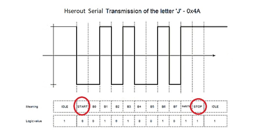
you don't quibble the hserout command adding start and stop bits to your serial transmission or even calculating the parity and inserting it also
why should the i2c "high level" commands not be able to set the r/w bit as required, after all that's why you use pbp. it stops you needing to dig into the bowels of i2c transactions
the manual
lets not hear any more of this nonsense
Last edited by richard; - 12th January 2022 at 23:57.
Warning I'm not a teacher
Thanks Richard,
just wanted to understand it. Now it is clear.
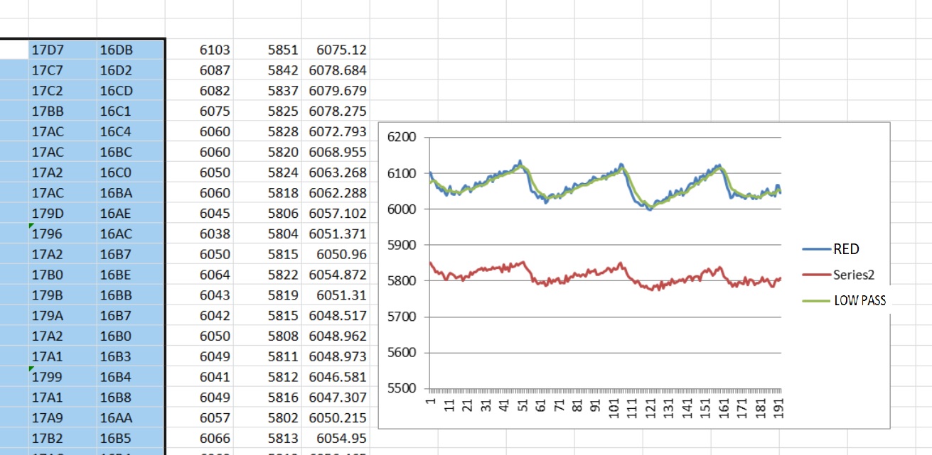
now have low pass filtering on pic
73 rpm tonight
Warning I'm not a teacher
That's really impressed Richard.
Im still working step by step on the code, im still at an early stage.
Just need to understand the methodology.
try as i might i cannot detect the relevant peaks reliably
Code:'****************************************************************'* Name : MAX30102 FOR PIC 18 DEMO * '* Author : Richard * '* Notice : * '* : * '* Date : 9/1/2022 * '* Version : 1.0 * '* Notes : MAX30102 * '* :18f26k22 @64Mhz * '**************************************************************** #CONFIG ; The PBP configuration for the PIC18F26K22 is: CONFIG FOSC = INTIO67 CONFIG PLLCFG = OFF ;Oscillator multiplied by 4 CONFIG PRICLKEN = ON ;Primary clock enabled CONFIG FCMEN = OFF ;Fail-Safe Clock Monitor disabled CONFIG IESO = OFF ;Oscillator Switchover mode disabled CONFIG BOREN = SBORDIS ; Brown-out Reset enabled in hardware only (SBOREN is disabled) CONFIG WDTEN = ON ; WDT is always enabled. SWDTEN bit has no effect ;| CONFIG WDTPS = 32768 ; 1:32768 ---> HERE enable the watchdog timer with a 1:32768 postscale;| CONFIG PWRTEN = ON CONFIG HFOFST = ON ; HFINTOSC output and ready status are not delayed by the oscillator stable status CONFIG MCLRE = EXTMCLR ; MCLR pin enabled, RE3 input pin disabled CONFIG LVP = OFF ; Single-Supply ICSP disabled CONFIG XINST = OFF ; Instruction set extension and Indexed Addressing mode disabled (Legacy mode) CONFIG DEBUG = OFF ; Disabled CONFIG CP0 = OFF ; Block 0 (000800-003FFFh) not code-protected CONFIG CP1 = OFF ; Block 1 (004000-007FFFh) not code-protected CONFIG CP2 = OFF ; Block 2 (008000-00BFFFh) not code-protected CONFIG CP3 = OFF ; Block 3 (00C000-00FFFFh) not code-protected CONFIG CPB = OFF ; Boot block (000000-0007FFh) not code-protected CONFIG CPD = OFF ; Data EEPROM not code-protected CONFIG WRT0 = OFF ; Block 0 (000800-003FFFh) not write-protected CONFIG WRT1 = OFF ; Block 1 (004000-007FFFh) not write-protected CONFIG WRT2 = OFF ; Block 2 (008000-00BFFFh) not write-protected CONFIG WRT3 = OFF ; Block 3 (00C000-00FFFFh) not write-protected CONFIG WRTC = OFF ; Configuration registers (300000-3000FFh) not write-protected CONFIG WRTB = OFF ; Boot Block (000000-0007FFh) not write-protected CONFIG WRTD = OFF ; Data EEPROM not write-protected CONFIG EBTR0 = OFF ; Block 0 (000800-003FFFh) not protected from table reads executed in other blocks CONFIG EBTR1 = OFF ; Block 1 (004000-007FFFh) not protected from table reads executed in other blocks CONFIG EBTR2 = OFF ; Block 2 (008000-00BFFFh) not protected from table reads executed in other blocks CONFIG EBTR3 = OFF ; Block 3 (00C000-00FFFFh) not protected from table reads executed in other blocks CONFIG EBTRB = OFF ; Boot Block (000000-0007FFh) not protected from table reads executed in other blocks #ENDCONFIG goto overasm asm PutMulResult?D macro Din MOVE?BB Din, R2 MOVE?BB Din + 1, R2 + 1 MOVE?BB Din + 2, R0 MOVE?BB Din + 3, R0 + 1 RST?RP endm endasm overasm: define OSC 64 OSCCON = %01110000 ; 16Mhz OSCTUNE.6 = 1 ; Enable 4x PLL while ! osccon2.7 :WEND ; to make sure the pll has stabilised before you run any other code TRISC = %11011000 ANSELC=0 ANSELB=0 #DEFINE DEBUGING 1 DEFINE DEBUG_REG PORTB DEFINE DEBUG_BIT 7 DEFINE DEBUG_BAUD 9600 DEFINE DEBUG_MODE 0 SDA var portc.4 SCL VAR portc.3 reg var BYTE fifo var byte[6] bank0 addr var byte REVISION var byte PARTID var byte buffer var word[384] ptr var byte btr var byte index var word average var byte[4] bank0 ave var word peaks var byte[5] lastpeak var word lpfdata var word[192] result var word ext result1 var word ext @result = _fifo @result1 = _fifo + 3 ;----------------------- REGISTER ------------------------- REG_TEMP_INT con $1F REG_TEMP_FRAC con $20 REG_TEMP_CONFIG con $21 REG_PART_REVISION con $FE REG_MODE con $09 REG_SPO2_CONFIG con $0A ;SPO2_ADC_RGE[6:5]SPO2_SR[4:2]LED_PW[1:0] REG_LED1_PA con $0C REG_LED2_PA con $0D FIFO_WR_PTR con $04 ;FIFO_WR_PTR[4:0] FIFO_RD_PTR con $06 FIFO_DATA con $07 FIFO_CONFIG con $08 ;FIFO_A_FULL[3:0] SMP_AVE[7:5] OVF_COUNTER con $05 STATUS1 con 0 ;A_FULL[7] INTERRUPT_EN con 2 ' -----------------------------------------------------------------------------| #IFDEF DEBUGING LATB.7=1 PAUSE 2000 DEBUG 13,10, "READY" #ENDIF ADDR = $ae ; addr is 0x57 << 1 reg = REG_PART_REVISION i2cread SDA,scl,ADDR,reg,[REVISION,PARTID] reg = REG_MODE i2cwrite SDA,scl,ADDR,reg,[3] reg = REG_SPO2_CONFIG i2cwrite SDA,scl,ADDR,reg,[$20] reg = REG_LED2_PA i2cwrite SDA,scl,ADDR,reg,[10] reg = REG_LED1_PA i2cwrite SDA,scl,ADDR,reg,[10] reg = FIFO_CONFIG i2cwrite SDA,scl,ADDR,reg,[16] reg = INTERRUPT_EN i2cwrite SDA,scl,ADDR,reg,[$E0] DEBUG 13,10, "PART ID: 0X",hex PARTID,"/0X",hex REVISION start: reg= REG_TEMP_CONFIG i2cwrite SDA,scl,ADDR,reg,[1] reg= REG_TEMP_INT i2cread sda,scl,ADDR,reg,[fifo[0],fifo[1]] DEBUG 13,10, "TEMP: ",DEC fifo[0],".",DEC2( fifo[1]<<6) GOSUB AQUIRE pause 2000 goto start aquire: reg= FIFO_WR_PTR i2cwrite SDA,scl,ADDR,reg,[0] reg= FIFO_RD_PTR i2cwrite SDA,scl,ADDR,reg,[0] reg = OVF_COUNTER i2cwrite sda,scl,ADDR,reg,[0] asm banksel 0 clrf _average clrf _average+1 clrf _average+2 clrf _average+3 endasm FOR index = 0 TO 255 STEP 0 btr = 0 reg = STATUS1 WHILE (btr & 192) = 0 i2cread sda,scl,ADDR,reg,[btr] WEND reg = FIFO_WR_PTR i2cread SDA,scl,ADDR,reg,[Ptr] reg = FIFO_RD_PTR i2cread SDA,scl,ADDR,reg,[btr] btr = (ptr - btr) & 31 WHILE btr reg = FIFO_DATA ;---------ir----------;===========red=========== i2cread sda,scl,ADDR,reg,[FIFO[5],FIFO[4],FIFO[3],FIFO[2],FIFO[1],FIFO[0]] asm ;ROTATE READING TO GET SUFFICIENT RESOLOUTION INTO lower WORD banksel 0 bcf STATUS,C RRCF _fifo + 2 ,f RRCF _fifo + 1 ,f RRCF _fifo ,f bcf STATUS,C RRCF _fifo + 2 ,f RRCF _fifo + 1 ,f RRCF _fifo ,f bcf STATUS,C RRCF _fifo + 5 ,f RRCF _fifo + 4 ,f RRCF _fifo + 3 ,f bcf STATUS,C RRCF _fifo + 5 ,f RRCF _fifo + 4 ,f RRCF _fifo + 3 ,f movf _fifo ,w ;RED AVERAGE addwf _average,f movf _fifo + 1 ,w bnc s1 incf _average + 1,f s1 addwf _average + 1,f movf _fifo + 2 ,w bnc s2 incf _average + 2,f s2 bnc s3 incf _average + 3 ,f s3 endasm buffer[index] = result ;red index = index + 1 buffer[index] = result1 ;ir index = index + 1 btr = btr - 1 WEND NEXT DEBUG 13,10,hex2 average[3],hex2 average[2],hex2 average[1],hex2 average @ PutMulResult?D _average ;RED AVERAGE ave = DIV32 128 ;RED AVERAGE reg = OVF_COUNTER i2cread sda,scl,ADDR,reg,[reg ] DEBUG 13,10,"OverFlows ",DEC reg,9,dec ave,9,hex ave FOR index = 0 TO 255 STEP 0 ave = (ave ** 62259) + (buffer[index] ** 3276 ) lpfdata[index>>1]=ave ;.....lpf..;;;;----red-----;;;;======-ir-======== DEBUG 13,10,dec ave,9,dec buffer[index],9,dec buffer[index+1] index = index + 2 NEXT RETURN
Warning I'm not a teacher

In Post #44 your low-pass filter seemed to work perfectly, then in Post #49, it seemed a bit overdone. Then in Post #51 it looks like the low-pass filter is acting like a 500F capacitor! I didn't look at the code, but maybe you could back off on the filter settings for a clearer reading.
i have tried many variations , the added aggressiveness of the filter is an attempt to remove the unwanted "little" peaksbut maybe you could back off on the filter settings for a clearer reading.
what looks like a nice picture of on a graph does not mean peak detection is easier.
some of the lp filtering is just added in with excel also, even tried using trend lines in attempt at detecting pos and neg zero crossings
that's still not 100% effective. dsp is not my forte, dc drift in the readings can be neg or pos going or both or zero.
fft was a failure because i cannot remove the dc component effectively. i need a better method i have no effective strategy
Warning I'm not a teacher
Here is a Filter algorithm that has served me well with several projects. For the moment I'm going to assume your code serves 2 main functions: read the heart rate MAX30102 and report the results. This means the processor execution time can be maximized for these 2 functions.
Reporting process is what it is. That's whatever protocol (UART, SPI, I2C, or LCDOUT etc) you have chosen to make use of the processed data.
As for reading and filtering the MAX30102 data, the first stage is to take multiple ADC reads (or appropriately retrieve the latest data report) each Subroutine CALL and average them. The result gets fed into a circular buffer, where the average is the last X readings, and what you shoot out in your report. It looks something like this:
Somewhere a CALL (GOSUB) is made to check the input from the MAX30102 sensor. Within the Subroutine, you do this 4X and average the results. The average result is fed into a [4] BYTE/WORD circular buffer. An Accumulator adds all buffer entries and divides the result by the number of entries (calculates an average). The value reported is the average of the circular buffer -- buffered value. With me so far? Let's take it for a test drive, shall we?
To change the impact of the filter, you can increase or decrease the size of the HrValBuf[4] buffer and/or the HrValCir[4] buffer. If too jumpy, add more entries for either/both buffer(s). Conversely, to economize, try reducing buffer sizes and see if you still like the results. Changes would have to be reflected in Get_Heartrate:. No, of course this isn't the absolute most efficient code to accomplish the goal, and it is too abbreviated to actually work, but I hope it illustrates an effective filter that has served me well over many projects.Code:b0 VAR BYTE ;Used for FOR/LOOP HrVal VAR BYTE ;if using 8-bit ADC, ...VAR WORD for 10-bit, or whatever protocol demands HrValBuf VAR BYTE[4] ;again, WORD for 10-bit, this is your 4 immediate ADC (MAX30102 input) reads Buffer HrValCir VAR BYTE[4] ;again, WORD for 10-bit, this is your 4 entry Circular Buffer HrBufAcc VAR WORD ;Total of all 4 HrValBuf readings HrCirAcc Var WORD ;Total of all 4 HrCirBuf readings HeartRate VAR BYTE ;again, WORD for 10-bit, End Filtered Result to be Reported or Processed ... ;from Somewhere in Code: GOSUB Get_HeartRate GOSUB Send_HeartRate ;Do something with the HeartRate Value Acquired & Filtered ... ;then Continue Code... Get_Heartrate: HrValCir[3] = HrValCir[2] ;Rotate the Circular Buffer HrValCir[2] = HrValCir[1] HrValCir[1] = HrValCir[0] FOR b0 = 0 TO 3 ADCIN MAX30102,HrVal ;or I2CREAD or SPIREAD -- Retrieve a Current Value HrValBuf[b0] = HrVal NEXT b0 HrBufAcc = HrValBuf[3] + HrValBuf[2] + HrValBuf[1] + HrValBuf[0] ;Add All 4 Readings... HrValCir[0] = HrBufAcc >> 2 ;Same as HrValCir[0] = HrBufAcc / 4 -- Places the Latest Averaged Value into the Circular Buffer HrCirAcc = HrValCir[3] + HrValCir[2] + HrValCir[1] + HrValCir[0] ;Totals the Circular Buffer HeartRate = HrCirAcc >> 2 ;Same as HeartRate = HrCirAcc / 4, Averages the Circular Buffer RETURN
Last edited by mpgmike; - 15th January 2022 at 01:52.
the filter is not really the issue, its the variability of the data that is problematical, every 128 sample is subtly different.
light leakage, finger pressure and position and even finger compression time lead to wildly variable readings. my max30102 housing is probable not ideal either
i use for this filter
fv = fv*x + nv*(y)
where x+y = 1, fv = average nv = new value
in pbp terms x y
ave = (ave ** 60000) + (buffer[index] ** 5535 ) ;60000 + 5535 = 65535
or
ave = (ave */ 250) + (buffer[index] */ 5 ) ;250+ 5 = 255
depending on finesse required, the introduced phase shift has no bearing on the result either.
it may not be as fast as your method but has better control and in this case speed is of no importance
Last edited by richard; - 15th January 2022 at 04:49.
Warning I'm not a teacher
well my sensor was not 5v tolerant its now a random number generator , in the bin
i give up
Warning I'm not a teacher
Richard which sensor did you have? Could you please let us know? for avoiding it in the future.
Based on cardiovascular medical graph, the post #44 and post #49 looks fine.
I think #49 it is a bit better which doesnt mean the in #44 the graph is not acceptable.
my module was clearly marked as 3.3v its the one with slots in the board to tie it on your finger
the code has little if any effect on the graphical result. the result depends on your finger and its placement
ambient light etc, my holder is a little tight it constricts circulation a bit and i need to change fingers every 10 minutes to get good data
i found a spare [must have bought 2] i will be more careful with this one.
i still cannot get a algo to find the right peaks. on a graph it looks so obvious even in the crappy reads beats are distinctive, by the absolute shits computers are stupid. breaking the search into 32 sample blocks gets me the block highest highs and lowest lows but there is no guarantee the high in a block is actually a peak or whether continues to ramp up into the next block
Warning I'm not a teacher
I guess you have this one
https://www.teachmemicro.com/max3010...r-for-arduino/
I also have 2 of those, but in the schematic the input voltage is 3.3V to 5V.
or you are talking about the logic level? So i also need to take care about it and supply the PIC with 3.3V.
interesting mine has no jumper fitted, its not dead just gives random results , temp works ok still
led still comes on
i will solder the jumper and try again
Warning I'm not a teacher

It is very important to:
1. have the finger cleaned with alcohol before testing and also clean the sensor with alcohol too.
2. Not pressing hard the finger on the sensor, the shell of the sensor should be lightly tight on the finger.
3. No ambient light should come in the sensor area. Most if not all commercial devices are black for a purpose.
Hope this helps.
Ioannis
i cleaned the screen with metho it had a spec of gunge in the wrong spot now restored. mine will not run for long at 5v 3-4 minutes then the readings are crap, jumper made nil difference. i notice the led got substantially brighter when it goes strange. 5v is a no go for this unit
Warning I'm not a teacher
this kind of defines the problem
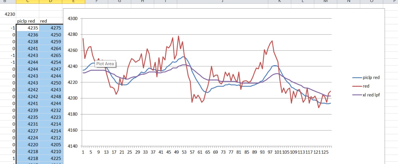
peaks are easy to see, my 32 sample search yields these peaks its not easy
sample
5
51
95
98
raw data
Code:lpf red ir 4235 4275 4435 4236 4250 4443 4238 4259 4440 4241 4264 4450 4243 4265 4482 4244 4254 4471 4244 4247 4446 4243 4244 4425 4243 4250 4424 4242 4243 4394 4242 4248 4397 4241 4244 4372 4239 4232 4376 4235 4223 4377 4231 4214 4375 4227 4214 4364 4224 4212 4385 4220 4205 4382 4218 4210 4403 4218 4225 4401 4217 4216 4398 4217 4229 4398 4217 4224 4400 4218 4238 4410 4220 4244 4412 4223 4250 4401 4225 4248 4398 4226 4245 4402 4228 4247 4398 4230 4248 4386 4233 4256 4402 4232 4238 4390 4233 4250 4400 4236 4262 4405 4238 4256 4400 4237 4237 4405 4236 4235 4400 4236 4245 4420 4234 4227 4431 4235 4251 4442 4234 4234 4437 4235 4252 4432 4236 4248 4420 4239 4265 4455 4241 4263 4440 4243 4267 4436 4246 4276 4439 4245 4249 4424 4246 4255 4433 4249 4278 4442 4250 4262 4442 4252 4271 4427 4252 4254 4429 4250 4242 4408 4246 4228 4399 4241 4221 4399 4234 4195 4378 4229 4205 4378 4224 4200 4395 4220 4204 4381 4216 4200 4363 4212 4195 4377 4209 4198 4372 4208 4208 4365 4207 4215 4366 4209 4227 4375 4212 4240 4371 4213 4227 4371 4214 4229 4358 4215 4229 4353 4215 4220 4360 4215 4218 4356 4215 4222 4357 4217 4233 4365 4217 4228 4360 4218 4232 4366 4217 4222 4364 4217 4230 4366 4217 4224 4373 4216 4220 4391 4217 4233 4381 4215 4211 4391 4215 4221 4401 4215 4222 4404 4215 4222 4411 4215 4220 4425 4215 4221 4418 4216 4226 4413 4217 4233 4427 4218 4238 4421 4219 4237 4416 4221 4245 4428 4222 4237 4421 4226 4261 4422 4229 4255 4436 4233 4263 4432 4236 4269 4437 4240 4272 4423 4241 4258 4431 4241 4252 4403 4240 4246 4381 4236 4223 4368 4231 4207 4343 4227 4213 4334 4223 4206 4341 4220 4211 4338 4218 4213 4334 4214 4194 4325 4213 4209 4336 4211 4201 4326 4210 4210 4328 4209 4211 4327 4207 4205 4321 4205 4195 4332 4203 4199 4324 4203 4213 4349 4201 4194 4352 4200 4202 4341 4198 4200 4338 4198 4203 4333 4197 4197 4348 4195 4188 4356 4194 4194 4377 4194 4204 4371 4194 4202 4383 4193 4195 4408 4193 4206 4383 4194 4209 4387
Warning I'm not a teacher
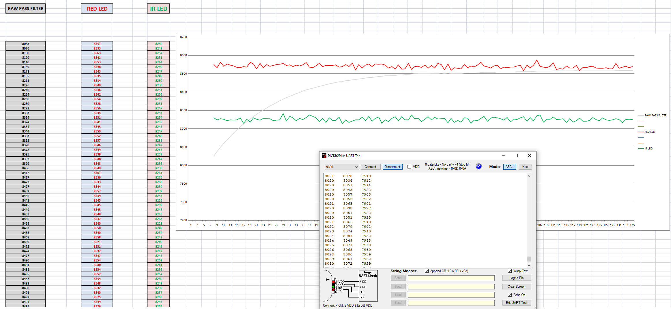
results from PICKIT UART TOOL at 9600.
Code:RED IR 8875 9120 8859 9127 8867 9128 8868 9127 8871 9116 8875 9121 8880 9115 8873 9115 8870 9115 8876 9123 8881 9127 8880 9114 8875 9118 8877 9129 8873 9114 8879 9127 8895 9119 8879 9129 8870 9128 8880 9130 8897 9139 8888 9116 8880 9123 8886 9146 8889 9124 8890 9119 8897 9113 8891 9122 8872 9134 8896 9124 8885 9121 8875 9121 8882 9130 8885 9129 8892 9125 8894 9132 8884 9117 8888 9127 8881 9116 8878 9124 8876 9112 8864 9117 8873 9120 8867 9113 8879 9123 8873 9125 8865 9119 8872 9131 8873 9118 8878 9124 8877 9123 8878 9119 8878 9116 8891 9108 8878 9110 8869 9140 8877 9119 8870 9119 8865 9116 8878 9120 8882 9126 8884 9138 8877 9130 8879 9116 8883 9127 8883 9128 8887 9140 8890 9126 8876 9107 8884 9116 8875 9121 8888 9138 8893 9117 8885 9116 8895 9114 8876 9128 8891 9128 8893 9130 8889 9123 8881 9114 8886 9119 8876 9116 8883 9126 8876 9118 8875 9126 8866 9115 8882 9115 8866 9113 8882 9118 8880 9118 8885 9108 8877 9123 8880 9125 8869 9122 8888 9123 8871 9119 8881 9118 8876 9117 8890 9136 8879 9115 8891 9124 8886 9115 8891 9107 8884 9110 8886 9128 8899 9117 8886 9138 8883 9133 8902 9130 8890 9132 8877 9124 8889 9131 8895 9127 8884 9132 8887 9127 8885 9120 8893 9139 8895 9135 8875 9131 8889 9109 8891 9110 8881 9121 8875 9123 8889 9126 8867 9124 8873 9111 8875 9115 8875 9109 8865 9102 8874 9119 8890 9124 8886 9121 8879 9115 8877 9114 8876 9118 8878 9106 8867 9114 8874 9110 8881 9121 8877 9120 8885 9113 8873 9107 8889 9127 8876 9127 8889 9115 8874 9110 8888 9119 8877 9131 8884 9108 8888 9114 8882 9116 8881 9110 8891 9113 8871 9114 8879 9107 8882 9115 8877 9115 8886 9114 8880 9118 8874 9100 8864 9112 8864 9112 8872 9102 8867 9114 8855 9092 8865 9117 8873 9104 8861 9115 8855 9113 8868 9099 8849 9098 8875 9109 8868 9111 8861 9108 8872 9100 8873 9113 8871 9123 8863 9100 8866 9110 8874 9106 8870 9102 8884 9100 8873 9117 8865 9109 8860 9111 8861 9117 8872 9102 8868 9107 8885 9111 8869 9098 8866 9116 8876 9106
The following is the circuit board, which is changed and added a 3.3V step up/ step down Voltage regulator. Just ot be on a safe side.
The following is a second measurement which based on a samsung's mobile measurement it suppose to be close at 78 bpm.
Code:RED IR 8492 8577 8489 8590 8493 8576 8494 8592 8500 8601 8499 8596 8509 8588 8504 8580 8504 8586 8514 8588 8507 8585 8504 8583 8513 8580 8514 8580 8517 8594 8514 8588 8512 8584 8499 8575 8507 8590 8514 8580 8499 8573 8505 8607 8504 8575 8489 8574 8498 8586 8496 8579 8510 8582 8498 8580 8499 8578 8537 8574 8505 8576 8497 8563 8503 8585 8500 8568 8488 8581 8505 8582 8506 8589 8521 8576 8497 8588 8509 8583 8507 8583 8499 8583 8497 8575 8502 8580 8486 8569 8505 8579 8507 8571 8499 8576 8505 8572 8502 8580 8498 8570 8499 8569 8496 8571 8485 8572 8496 8564 8511 8580 8499 8570 8498 8562 8497 8578 8499 8581 8493 8656 8497 8579 8503 8573 8507 8584 8492 8570 8499 8565 8495 8572 8501 8573 8511 8576 8502 8568 8506 8562 8499 8557 8498 8572 8492 8563 8505 8555 8503 8567 8494 8565 8493 8570 8502 8573 8489 8564 8493 8558 8507 8565 8505 8574 8499 8571 8497 8576 8493 8574 8489 8566 8498 8568 8496 8569 8495 8578 8517 8570 8515 8564 8506 8556 8509 8571 8506 8572 8497 8565 8508 8570 8499 8571 8506 8566 8443 8575 8498 8571 8501 8568 8500 8562 8512 8569 8497 8565 8510 8573 8499 8563 8508 8555 8526 8566 8513 8566 8513 8582 8505 8562 8511 8585 8492 8564 8511 8582 8514 8563 8502 8570 8506 8570 8518 8563 8513 8570 8508 8575 8505 8586 8510 8560 8519 8572 8516 8580 8511 8584 8506 8562 8496 8565 8519 8570 8502 8575 8631 8578 8510 8570 8529 8571 8516 8562 8515 8566 8510 8568 8514 8579 8513 8581 8518 8573 8524 8578 8504 8569 8508 8559 8515 8569 8515 8575 8512 8580 8514 8555 8525 8583 8519 8577 8517 8572 8507 8571 8516 8572 8521 8571 8525 8581 8505 8563 8522 8565 8518 8569 8516 8559 8515 8578 8521 8567 8502 8571 8522 8577 8528 8586 8529 8581 8518 8579 8507 8562 8520 8571 8512 8560 8518 8572 8531 8550 8507 8576 8503 8568 8515 8578 8509 8573 8518 8570 8517 8566 8508 8567 8509 8570 8520 8572 8518 8585 8513 8565 8521 8566 8525 8569 8515 8578 8515 8573 8517 8567 8515 8578 8510 8565 8515 8572 8531 8564 8516 8563 8519 8560 8514 8571
Last edited by astanapane; - 15th January 2022 at 12:44.
For everyone info,
found this interesting article.
https://morf.lv/implementing-pulse-o...using-max30100
wrong info above, as i captured ascii and not hex values.
I'll try to fix that on the following message.
if you are using excel then its easier to import dec rather than hex, i changed to dec
Warning I'm not a teacher
just tried. Let me see the values on the excel.
Code:0 8028 1F5C 8053 8551 8259 8076 8533 8249 8100 8563 8254 8120 8541 8251 8140 8553 8244 8159 8548 8249 8178 8543 8247 8195 8535 8249 8211 8534 8260 8226 8540 8230 8240 8536 8251 8254 8562 8236 8268 8554 8259 8280 8528 8251 8292 8556 8247 8303 8534 8257 8314 8551 8254 8324 8541 8255 8334 8545 8243 8344 8550 8247 8353 8552 8248 8362 8557 8283 8370 8546 8242 8378 8549 8267 8385 8539 8259 8392 8548 8244 8399 8543 8256 8406 8549 8250 8412 8561 8261 8417 8536 8275 8422 8533 8268 8427 8544 8259 8432 8557 8239 8436 8539 8257 8441 8545 8235 8445 8545 8259 8449 8545 8245 8453 8549 8245 8456 8537 8263 8459 8540 8228 8463 8550 8249 8465 8540 8234 8468 8558 8242 8469 8521 8249 8472 8551 8249 8474 8532 8262 8477 8547 8243 8480 8554 8268 8481 8540 8241 8483 8554 8256 8485 8552 8264 8487 8554 8230 8489 8548 8249 8490 8532 8239 8491 8540 8257 8492 8525 8265 8494 8549 8243 8495 8526 8265 8496 8527 8249 8498 8556 8249 8499 8524 8275 8500 8539 8255 8500 8541 8257 8500 8535 8239 8501 8547 8251 8501 8530 8266 8502 8546 8248 8502 8532 8262 8503 8557 8253 8504 8551 8254 8503 8522 8257 8504 8554 8233 8503 8519 8256 8503 8534 8234 8503 8530 8246 8503 8528 8236 8504 8550 8259 8504 8534 8258 8504 8542 8229 8504 8538 8247 8505 8548 8243 8507 8563 8256 8508 8543 8267 8508 8538 8241 8508 8532 8258 8509 8543 8263 8510 8547 8259 8510 8527 8254 8510 8536 8247 8510 8534 8261 8510 8537 8238 8510 8536 8253 8511 8543 8250 8512 8546 8260 8511 8518 8266 8512 8548 8240 8512 8533 8261 8513 8545 8242 8515 8575 8270 8515 8541 8275 8515 8536 8236 8515 8534 8252 8515 8541 8251 8516 8559 8264 8516 8524 8250 8516 8529 8251 8516 8526 8254 8517 8543 8235 8517 8532 8254 8517 8532 8236 8518 8545 8243 8517 8518 8258 8517 8535 8240 8517 8534 8241 8517 8539 8245 8517 8541 8261 8517 8532 8250 8517 8531 8243 8517 8530 8260 8517 8534 8249 8517 8528 8246 8517 8527 8249 8518 8557 8255 8518 8531 8250 8518 8537 8233 8518 8541 8250 8518 8534 8252 8518 8539 8250
Just transfered those values from the PICKIT serial terminal to excel. No conversion.
Last edited by astanapane; - 16th January 2022 at 01:10.
tidied up a bit and swaped to using ir data [still in mode 3 for now]
Code:'****************************************************************'* Name : MAX30102 FOR PIC 18 DEMO * '* Author : Richard * '* Notice : * '* : * '* Date : 9/1/2022 * '* Version : 1.0 * '* Notes : MAX30102 * '* :18f26k22 @64Mhz * '**************************************************************** #CONFIG ; The PBP configuration for the PIC18F26K22 is: CONFIG FOSC = INTIO67 CONFIG PLLCFG = OFF ;Oscillator multiplied by 4 CONFIG PRICLKEN = ON ;Primary clock enabled CONFIG FCMEN = OFF ;Fail-Safe Clock Monitor disabled CONFIG IESO = OFF ;Oscillator Switchover mode disabled CONFIG BOREN = SBORDIS ; Brown-out Reset enabled in hardware only (SBOREN is disabled) CONFIG WDTEN = ON ; WDT is always enabled. SWDTEN bit has no effect ;| CONFIG WDTPS = 32768 ; 1:32768 ---> HERE enable the watchdog timer with a 1:32768 postscale;| CONFIG PWRTEN = ON CONFIG HFOFST = ON ; HFINTOSC output and ready status are not delayed by the oscillator stable status CONFIG MCLRE = EXTMCLR ; MCLR pin enabled, RE3 input pin disabled CONFIG LVP = OFF ; Single-Supply ICSP disabled CONFIG XINST = OFF ; Instruction set extension and Indexed Addressing mode disabled (Legacy mode) CONFIG DEBUG = OFF ; Disabled CONFIG CP0 = OFF ; Block 0 (000800-003FFFh) not code-protected CONFIG CP1 = OFF ; Block 1 (004000-007FFFh) not code-protected CONFIG CP2 = OFF ; Block 2 (008000-00BFFFh) not code-protected CONFIG CP3 = OFF ; Block 3 (00C000-00FFFFh) not code-protected CONFIG CPB = OFF ; Boot block (000000-0007FFh) not code-protected CONFIG CPD = OFF ; Data EEPROM not code-protected CONFIG WRT0 = OFF ; Block 0 (000800-003FFFh) not write-protected CONFIG WRT1 = OFF ; Block 1 (004000-007FFFh) not write-protected CONFIG WRT2 = OFF ; Block 2 (008000-00BFFFh) not write-protected CONFIG WRT3 = OFF ; Block 3 (00C000-00FFFFh) not write-protected CONFIG WRTC = OFF ; Configuration registers (300000-3000FFh) not write-protected CONFIG WRTB = OFF ; Boot Block (000000-0007FFh) not write-protected CONFIG WRTD = OFF ; Data EEPROM not write-protected CONFIG EBTR0 = OFF ; Block 0 (000800-003FFFh) not protected from table reads executed in other blocks CONFIG EBTR1 = OFF ; Block 1 (004000-007FFFh) not protected from table reads executed in other blocks CONFIG EBTR2 = OFF ; Block 2 (008000-00BFFFh) not protected from table reads executed in other blocks CONFIG EBTR3 = OFF ; Block 3 (00C000-00FFFFh) not protected from table reads executed in other blocks CONFIG EBTRB = OFF ; Boot Block (000000-0007FFh) not protected from table reads executed in other blocks #ENDCONFIG goto overasm asm PutMulResult?D macro Din MOVE?BB Din, R2 MOVE?BB Din + 1, R2 + 1 MOVE?BB Din + 2, R0 MOVE?BB Din + 3, R0 + 1 RST?RP endm endasm overasm: define OSC 64 OSCCON = %01110000 ; 16Mhz OSCTUNE.6 = 1 ; Enable 4x PLL while ! osccon2.7 :WEND ; to make sure the pll has stabilised before you run any other code TRISC = %11011000 ANSELC=0 ANSELB=0 #DEFINE DEBUGING 1 DEFINE DEBUG_REG PORTB DEFINE DEBUG_BIT 7 DEFINE DEBUG_BAUD 9600 DEFINE DEBUG_MODE 0 SDA var portc.4 SCL VAR portc.3 reg var BYTE fifo var byte[6] bank0 addr var byte REVISION var byte PARTID var byte buffer var word[384] ptr var byte btr var byte index var word average var byte[4] bank0 ave var word peaks var byte[8] lastpeak var word lastlow var word lpfdata var word[192] result var word ext result1 var word ext pulse var word @result = _fifo @result1 = _fifo + 3 ;----------------------- REGISTER ------------------------- REG_TEMP_INT con $1F REG_TEMP_FRAC con $20 REG_TEMP_CONFIG con $21 REG_PART_REVISION con $FE REG_MODE con $09 REG_SPO2_CONFIG con $0A ;SPO2_ADC_RGE[6:5]SPO2_SR[4:2]LED_PW[1:0] REG_LED1_PA con $0C REG_LED2_PA con $0D FIFO_WR_PTR con $04 ;FIFO_WR_PTR[4:0] FIFO_RD_PTR con $06 FIFO_DATA con $07 FIFO_CONFIG con $08 ;FIFO_A_FULL[3:0] SMP_AVE[7:5] OVF_COUNTER con $05 STATUS1 con 0 ;A_FULL[7] INTERRUPT_EN con 2 ' -----------------------------------------------------------------------------| #IFDEF DEBUGING LATB.7=1 PAUSE 2000 DEBUG 13,10, "READY" #ENDIF ADDR = $ae ; addr is 0x57 << 1 reg = REG_PART_REVISION i2cread SDA,scl,ADDR,reg,[REVISION,PARTID] reg = REG_MODE i2cwrite SDA,scl,ADDR,reg,[3] reg = REG_SPO2_CONFIG i2cwrite SDA,scl,ADDR,reg,[$20] reg = REG_LED2_PA i2cwrite SDA,scl,ADDR,reg,[10] reg = REG_LED1_PA i2cwrite SDA,scl,ADDR,reg,[10] reg = FIFO_CONFIG i2cwrite SDA,scl,ADDR,reg,[16] reg = INTERRUPT_EN i2cwrite SDA,scl,ADDR,reg,[$E0] DEBUG 13,10, "PART ID: 0X",hex PARTID,"/0X",hex REVISION start: reg= REG_TEMP_CONFIG i2cwrite SDA,scl,ADDR,reg,[1] reg= REG_TEMP_INT i2cread sda,scl,ADDR,reg,[fifo[0],fifo[1]] DEBUG 13,10, "TEMP: ",DEC fifo[0],".",DEC2( fifo[1]<<6) GOSUB AQUIRE pause 2000 goto start aquire: index=0 reg= FIFO_WR_PTR i2cwrite SDA,scl,ADDR,reg,[0] reg= FIFO_RD_PTR i2cwrite SDA,scl,ADDR,reg,[0] reg = OVF_COUNTER i2cwrite sda,scl,ADDR,reg,[0] asm banksel 0 clrf _average clrf _average+1 clrf _average+2 clrf _average+3 endasm while index <256 btr = 0 reg = STATUS1 WHILE (btr & 192) = 0 i2cread sda,scl,ADDR,reg,[btr] WEND reg = FIFO_WR_PTR i2cread SDA,scl,ADDR,reg,[Ptr] reg = FIFO_RD_PTR i2cread SDA,scl,ADDR,reg,[btr] btr = (ptr - btr) & 31 WHILE (btr && (index < 256)) reg = FIFO_DATA ;---------ir----------;===========red=========== i2cread sda,scl,ADDR,reg,[FIFO[2],FIFO[1],FIFO[0],FIFO[5],FIFO[4],FIFO[3]] asm ;ROTATE READING TO GET SUFFICIENT RESOLOUTION INTO lower WORD banksel 0 bcf STATUS,C RRCF _fifo + 2 ,f RRCF _fifo + 1 ,f RRCF _fifo ,f bcf STATUS,C RRCF _fifo + 2 ,f RRCF _fifo + 1 ,f RRCF _fifo ,f bcf STATUS,C RRCF _fifo + 5 ,f RRCF _fifo + 4 ,f RRCF _fifo + 3 ,f bcf STATUS,C RRCF _fifo + 5 ,f RRCF _fifo + 4 ,f RRCF _fifo + 3 ,f movf _fifo ,w ;RED AVERAGE addwf _average,f movf _fifo + 1 ,w btfsc STATUS,C incfsz _fifo + 1 ,w addwf _average + 1,f btfsc STATUS,C incf _average + 2,f endasm buffer[index] = result ;ir index = index + 1 buffer[index] = result1 ;red index = index + 1 btr = btr - 1 WEND wend DEBUG 13,10,hex2 average[3],hex2 average[2],hex2 average[1],hex2 average @ PutMulResult?D _average ;RED AVERAGE ave = DIV32 128 ;RED AVERAGE reg = OVF_COUNTER i2cread sda,scl,ADDR,reg,[reg ] DEBUG 13,10,"OverFlows ",DEC reg,9,dec ave,9,hex ave FOR index = 0 TO 255 step 2 ave = (ave ** 57000) + (buffer[index] ** 8535 ) lpfdata[index>>1]=ave ;.....lpf..;;;;----red-----;;;;======-ir-======== DEBUG 13,10,dec ave,9,dec buffer[index],9,dec buffer[index+1] NEXT ' RETURN lastpeak = lpfdata[0] lastlow = lpfdata[0] asm banksel _peaks clrf _peaks clrf _peaks+1 clrf _peaks+2 clrf _peaks+3 clrf _peaks+4 clrf _peaks+5 clrf _peaks+6 clrf _peaks+7 banksel 0 endasm DEBUG 13,10,"lpf" lastpeak = lpfdata[0] lastlow = lpfdata[0] for index = 0 TO 31 ;p1 if (lpfdata[index] > lastpeak) then lastpeak = lpfdata[index] peaks[4] = index :peaks[5]=index :peaks[6]=index :peaks[7]=index endif if (lpfdata[index] < lastlow) then lastlow = lpfdata[index] peaks[0] = index :peaks[1]=index :peaks[2]=index :peaks[3]=index endif NEXT lastpeak = lpfdata[32] lastlow = lpfdata[32] for index = 32 TO 63 ;p2 if (lpfdata[index] >lastpeak) then lastpeak = lpfdata[index] peaks[5] = index :peaks[6]=index :peaks[7]=index endif if (lpfdata[index] <lastlow) then lastlow = lpfdata[index] peaks[1] = index :peaks[2]=index :peaks[3]=index endif NEXT lastpeak = lpfdata[64] lastlow = lpfdata[64] for index = 64 TO 95 ;p3 if (lpfdata[index] >lastpeak) then lastpeak = lpfdata[index] peaks[6]= index :peaks[7]=index endif if (lpfdata[index] < lastlow) then lastlow= lpfdata[index] peaks[2]= index :peaks[3]=index endif NEXT lastpeak = lpfdata[96] lastlow = lpfdata[96] for index = 96 TO 127 ;p4 if (lpfdata[index] >lastpeak) then lastpeak = lpfdata[index] peaks[7] = index endif if (lpfdata[index] <lastlow) then lastlow = lpfdata[index] peaks[3] = index endif NEXT DEBUG 13,10,dec peaks[4],9,dec peaks[0];,9, dec lpfdata[peaks[0]]-lpfdata[peaks[1]] DEBUG 13,10,dec peaks[5],9,dec peaks[1] DEBUG 13,10,dec peaks[6],9,dec peaks[2] DEBUG 13,10,dec peaks[7],9,dec peaks[3] ' pulse = 3000/abs( btr-ptr) ' DEBUG 13,10,dec ptr , 9,dec btr , 9,dec pulse RETURN
Last edited by richard; - 16th January 2022 at 01:43.
Warning I'm not a teacher
Richard thanks for your effort.
These are the new results base on the last change on IR values.
Code:8744 8760 9019 8745 8759 8995 8743 8740 9001 8744 8754 9012 8746 8764 8991 8745 8751 9002 8745 8755 8986 8743 8744 9003 8742 8739 9008 8743 8756 9000 8743 8752 9008 8745 8763 9023 8746 8762 8973 8743 8738 9011 8742 8745 8982 8739 8728 8985 8736 8726 9005 8735 8738 8990 8733 8727 8996 8733 8741 9001 8732 8736 8986 8730 8726 8996 8731 8750 8999 8730 8731 8983 8728 8725 9024 8730 8751 9002 8727 8720 9014 8729 8748 9014 8731 8751 8986 8731 8742 8998 8732 8749 8989 8732 8741 9001 8734 8761 9010 8736 8757 9001 8733 8722 9026 8732 8736 9022 8734 8756 8978 8734 8741 8988 8735 8752 8991 8735 8743 9010 8738 8762 9018 8737 8745 8992 8738 8746 8991 8741 8771 8995 8739 8734 8996 8740 8756 9010 8740 8753 9009 8741 8754 9002 8742 8759 8991 8740 8733 9001 8741 8755 9001 8739 8735 8978 8737 8733 8997 8738 8746 8981 8734 8720 8992 8733 8732 9004 8732 8735 8981 8730 8725 9004 8731 8750 8979 8730 8735 8983 8730 8743 8986 8730 8742 8982 8729 8732 8989 8731 8748 9004 8732 8752 8981 8728 8715 8981 8730 8748 9002 8729 8732 8999 8732 8758 9003 8732 8742 8990 8733 8747 9005 8734 8752 8991 8734 8742 8993 8736 8756 9007 8737 8753 8988 8737 8739 9004 8738 8750 8992 8737 8745 8993 8739 8759 9003 8740 8754 8975 8739 8743 8987 8740 8754 8996 8739 8743 8998 8741 8763 8999 8741 8749 8978 8740 8743 8996 8741 8756 8987 8740 8740 8993 8740 8747 9005 8739 8742 8977 8735 8720 8977 8734 8737 8984 8733 8732 8985 8733 8739 8986 8733 8743 8982 8730 8722 8990 8728 8729 8986 8726 8717 8999 8726 8731 8988 8726 8735 8983 8725 8729 8987 8727 8751 8989 8727 8732 8976 8727 8733 8997 8729 8751 8988 8730 8740 9005 8731 8749 8983 8732 8750 8984 8734 8755 8997 8737 8766 8971 8736 8733 8986 8738 8760 8969 8737 8740 8990 8740 8762 9001 8741 8755 8973 8739 8735 8997 8740 8761 8971 8740 8747 8985 8741 8758 8974 8740 8744 8990 8742 8763 9014 8744 8763 8977 8741 8727 8978 8739 8732 8981 8737 8734 8980 8736 8736 8988 8736 8742 8964 8733 8717 8974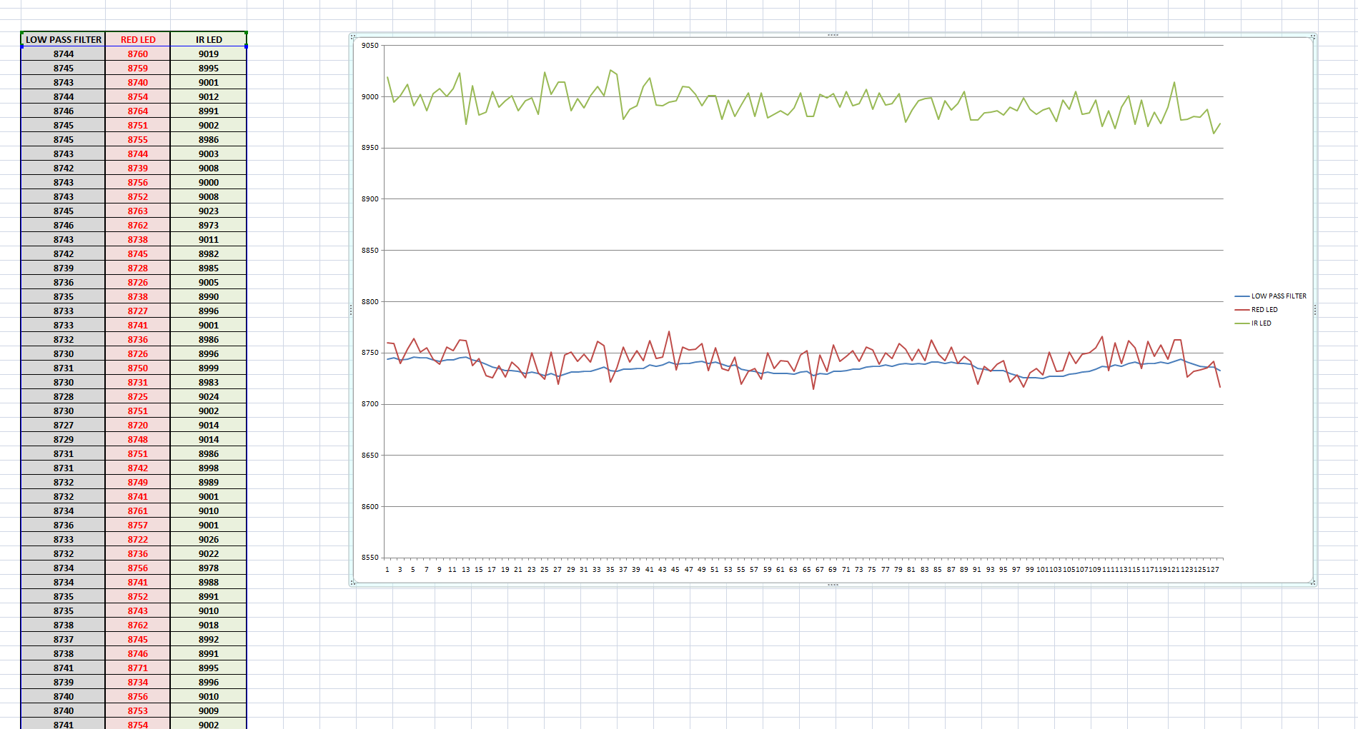
Richard,
i think i post #41 and #44, the graph was a bit better in terms of highs and lows. Dont know if the last configuration and modification in LPF made it easier to identify those highs and lows.
Have you checked to see if you actually have a pulse for this thing to read? Maybe you're dead and don't even know it?? Try it on someone else as a verification? Just joking...
hehehehe, sure i will do that. Just to check what will be the values on a different person, as i know my average Heart pulses are always around 82-90 Bpm.
I will find someone with much lower and more normal heart pulses like 62-75 bpm.
The following is my measurement right now.
(measured as well with the Samsung Galaxy Sensor 80 Bpm)Code:lpf 31 11 63 11 68 83 68 109 TEMP: 22.68 000F7E26 OverFlows 0 7932 1EFC 7928 7915 7838 7927 7925 7843 7926 7929 7818 7924 7921 7833 7924 7938 7815 7924 7933 7810 7919 7899 7812 7917 7916 7824 7919 7940 7811 7917 7916 7819 7918 7936 7825 7918 7928 7810 7918 7930 7820 7918 7930 7813 7918 7931 7813 7918 7926 7823 7919 7933 7812 7920 7935 7824 7921 7932 7821 7922 7935 7820 7921 7923 7823 7920 7922 7828 7921 7932 7825 7923 7943 7815 7922 7921 7819 7923 7939 7810 7924 7936 7823 7923 7925 7828 7926 7950 7827 7924 7923 7825 7924 7936 7821 7925 7942 7836 7923 7924 7812 7922 7921 7824 7924 7943 7818 7923 7929 7813 7924 7935 7825 7924 7933 7830 7922 7917 7824 7924 7943 7831 7925 7946 7811 7924 7928 7822 7924 7938 7839 7926 7952 7803 7925 7928 7827 7926 7941 7839 7927 7947 7819 7924 7916 7816 7927 7957 7842 7930 7958 7826 7930 7933 7820 7930 7932 7822 7931 7947 7821 7929 7925 7825 7930 7943 7827 7930 7935 7814 7928 7918 7840 7928 7936 7818 7927 7929 7827 7925 7919 7829 7925 7937 7819 7926 7946 7822 7926 7936 7812 7925 7929 7828 7925 7938 7827 7925 7933 7816 7925 7936 7834 7925 7938 7822 7928 7957 7821 7927 7928 7820 7928 7940 7809 7929 7942 7814 7927 7918 7830 7927 7938 7802 7926 7925 7814 7926 7932 7825 7926 7932 7813 7924 7923 7809 7924 7936 7830 7925 7940 7831 7926 7942 7824 7925 7926 7826 7923 7924 7811 7923 7928 7826 7926 7950 7834 7925 7930 7808 7924 7930 7826 7924 7932 7842 7926 7948 7807 7926 7934 7817 7927 7941 7831 7927 7937 7815 7925 7917 7833 7926 7945 7813 7926 7932 7796 7924 7922 7818 7924 7939 7806 7922 7921 7812 7924 7940 7811 7924 7936 7808 7922 7918 7821 7921 7924 7823 7923 7943 7804 7923 7925 7809 7924 7934 7817 7924 7939 7815 7923 7931 7806 7921 7915 7816 7921 7925 7809 7920 7923 7822 7920 7925 7822 7922 7947 7808 7922 7925 7817 7922 7929 7817 7922 7928 7820 7922 7926 7823 7923 7933 7832 7927 7959 7804 7925 7919 7812 7926 7942 7822 7924 7918 7809 7924 7935 7818 7924 7936 7813 7922 7923 7813 7923 7937 7818 7925 7941 7801 7922 7914 7818 7922 7929 7836 lpf 0 7 52 33 71 82 117 109 TEMP: 24.96
Last edited by astanapane; - 17th January 2022 at 22:40.
looks like simplistic lowpass filtering of the data to obtain pulse will never give a
reliable and repeatable result, it can deliver a nice picture but that is as far as it goes.
i will need to learn a bit more about dsp techniques. first step, remove dc component i think.
don't hold your breath, got more paid work this week
Warning I'm not a teacher
Richard this is already lots of work, and i dont know how to thank you for all this.
I believe that this will be useful for many people in the forum in the end. (even if noone else is involved).
I think Richard is eluding to a process called Fast Fourier Transform, FFT for short. The filter is a mathematical equation applied to each result. In many cases, the previous result is part of the equation. FFT is used to filter noise out of cell phone signals, among other things. The magic is getting the FFT formula right for your application. I've looked into it briefly, just enough to get an idea of what it's about, but not enough to actually use it effectively. I do know there are "standard" FFTs that are go-to works-every-time-its-tried that would probably work for you.
The one that is like Example #1 in the textbooks is simply:
This simply plots trends of increasing or decreasing values, without specific concern for the actual value.Code:if Result > Previous Plot += 1 elseif Result < Previous Plot -= 1 endif Previous = Result
been there done that.I think Richard is eluding to a process called Fast Fourier Transform
there is plenty of raw data posted, you can always ask for more. feel free to have a goThe one that is like Example #1 in the textbooks is simply:
Last edited by richard; - 19th January 2022 at 22:22.
Warning I'm not a teacher
Thanks for the generous offer
I did an other test on a different person. Those info are from a woman.
Richard have done a very good job up to now. I think the LPF should not be so aggressive.
Code:LPF RED IR 7278 7275 7077 7277 7266 7038 7275 7252 7048 7273 7242 7018 7270 7233 7012 7268 7247 7003 7266 7243 6991 7264 7248 6987 7263 7264 7005 7260 7231 7002 7257 7239 7008 7256 7242 7025 7256 7264 7015 7255 7249 7039 7255 7262 7037 7255 7267 7062 7254 7258 7047 7255 7286 7075 7255 7274 7086 7256 7289 7082 7257 7289 7096 7257 7281 7083 7257 7280 7105 7258 7284 7089 7259 7293 7124 7260 7291 7150 7260 7299 7122 7260 7299 7144 7261 7303 7143 7263 7329 7164 7264 7308 7173 7265 7307 7183 7266 7313 7163 7268 7322 7167 7269 7317 7171 7270 7317 7193 7273 7343 7198 7275 7329 7205 7277 7332 7194 7279 7330 7224 7281 7333 7201 7281 7318 7166 7280 7282 7125 7278 7265 7068 7276 7245 7029 7273 7240 7003 7270 7226 7016 7267 7234 6989 7263 7210 6988 7259 7209 6977 7257 7239 6970 7254 7221 6966 7252 7227 6977 7249 7214 6998 7247 7223 6998 7245 7233 6996 7243 7238 6996 7241 7239 7010 7239 7241 6995 7238 7233 7028 7237 7228 7036 7237 7261 7039 7236 7240 7049 7237 7262 7052 7237 7248 7062 7238 7265 7085 7239 7278 7108 7241 7286 7106 7242 7294 7136 7243 7286 7141 7244 7299 7148 7246 7302 7182 7248 7309 7159 7250 7318 7173 7252 7306 7192 7255 7331 7192 7256 7296 7212 7259 7329 7187 7261 7308 7226 7263 7338 7212 7265 7323 7224 7267 7327 7225 7269 7341 7225 7270 7305 7198 7270 7294 7140 7268 7256 7103 7266 7243 7041 7263 7241 7053 7260 7240 7029 7257 7234 7023 7255 7229 7021 7254 7245 7008 7251 7217 7044 7250 7243 7013 7248 7237 7033 7247 7245 7045 7247 7265 7060 7246 7255 7066 7246 7263 7070 7246 7265 7096 7246 7272 7075 7245 7260 7100 7245 7281 7103 7246 7287 7113 7246 7281 7131 7247 7288 7130 7248 7282 7159 7250 7306 7147 7251 7296 7171 7253 7319 7173 7255 7314 7190 7257 7314 7191 7260 7324 7204 7261 7302 7234 7263 7331 7204 7265 7323 7222 7266 7316 7215 7268 7329 7238 7269 7305 7243 7271 7339 7232 7273 7335 7243 7276 7348 7232 7278 7333 7257 7280 7325 7248 7281 7325 7229 7279 7278 7144 7277 7259 7086 7275 7244 7065
 Members who have read this thread : 0
You do not have permission to view the list of names.
 Posting Permissions
Bookmarks