Connect One Ethernet shield


Results 1 to 40 of 57

Threaded View

  1. #20
    Join Date
    Dec 2005
    Posts
    1,073

    Default Re: Connect One Ethernet shield

    Quote Originally Posted by mackrackit View Post
    The thing that looks wrong, and it is probably the way I am looking at the drawing. When looking down my module with the RJ45 to the right, the serial pins are on the upper header, J7. To me it looks like your drawings show a view from the bottom of both layers. Putting the RJ45 over the EEPROM...
    That's possible - I was using the pinouts from the data sheets and they may be top views when I was thinking the opposite (or vice versa). Try it with the RJ11 on the left, using the top (coppertone) view.

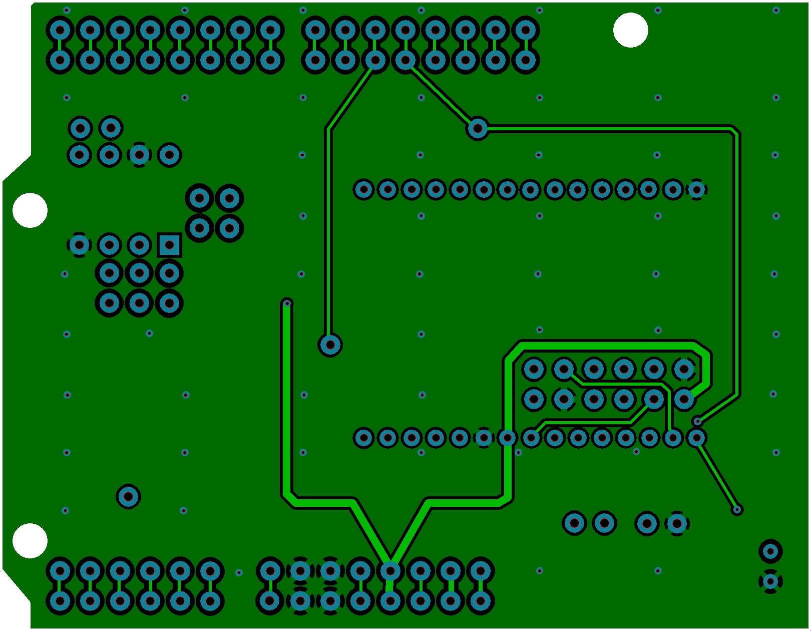
    Here's the latest layout. Can you reduce the size the way scalerobotics was doing? If I do it in Paint Shop Pro, it loses too much detail.
    Click image for larger version

Name:	TOP.JPG
Views:	4057
Size:	448.6 KB
ID:	5608Click image for larger version

Name:	BOTTOM.JPG
Views:	3973
Size:	247.4 KB
ID:	5609
    Last edited by ScaleRobotics; - 1st June 2011 at 14:18. Reason: scaling

Members who have read this thread : 0

You do not have permission to view the list of names.

Posting Permissions

  • You may not post new threads
  • You may not post replies
  • You may not post attachments
  • You may not edit your posts