


I will try to get a chance to study them in the next day or so. Got a client with a problem... luckily it is not on one of my systems

I will try to get a chance to study them in the next day or so. Got a client with a problem... luckily it is not on one of my systems
Dave
Always wear safety glasses while programming.

PM me with your email and I'll email the line drawings I made. You can check them against the datasheets and, if they jibe, check them against the layout .PNGsOriginally Posted by mackrackit

I have offered the Gerbers to Connect One in exchange for their reviewing the layout. Stay tuned.
Last edited by dhouston; - 3rd June 2011 at 18:26.

Why the offset square pads?
Why not place them at right angles, or make them round?
The one on the left above the I2C eeprom looks like a recipe for disaster (from a home-brewed PCB perspective).

Hi,
I had decided not to stick my nose into this but I'm going to anyway....
What are the reasons for not using the USART pins but instead using some ordinary I/O pins for serial in and out? The USARTs RX and TX pins are on 00 and 01 on the AMICUS18 which is what this forum section is about. Taking a quick look at the XINO Basic it TOO lists pins 00 and 01 as the USART RX and TX pins when used with the PICAXE chips listed there.
The PICAXE28X2 is just an 18F25K22 with some firmware so it TOO has the USART pins on RC6 and RC7 which then connects to pins 0 and 1. The AMICUS18 uses the 25K20 which also have the USART on RC6 and RC7.
Are these devices (nanoSocketLAN) not meant to be connected directly to a microcontroler with an USART thus expecting "true" data? Is the reason for not using the USART that they expect inverted data (I can't imagine that) and therfor you are using plain I/O and bit-banged serial where the polarity can be inverted instead of the microcontrolers onbaord USART?
I know you're providing pads so it can be re-wired but there must be a very specific reason for not wiring RX and TX to microcontrolers USART where they belong.
/Henrik.
The ConnectOne uses TRUE mode.
I like to leave the USART open for interruptible input to the MCU.
Dave
Always wear safety glasses while programming.
It's mostly because the various bootloaders are coded to use the hardware USART. And, I tend to think of these as development systems for READ (Rapid Embedded Application Development) where there will be a lot of changes, trials, errors, etc. rather than as finished products that stand on their own although they can certainly be used that way, as well.
DISCLAIMER: This thread and the Tibbo thread were not intended to disparage your WizNET approach. I'm just of the opinion that most folk are as lazy as me and use various Basic dialects so they don't have to learn ASM, C, etc. In that vein, both the ConnectOne and Tibbo modules do most of the heavy lifting that you're doing with SPI in your thread, making life easier for those of us inclined to take the easy way out. The Tibbo module requires coding but it's all in another Basic dialect and gets loaded as firmware into the Tibbo module rather than using much code space in the MCU be it PIC, PICAXE, Arduino AVR, or ZBasic AVR. And, it was fairly easy to design the shields so all the various modules (except for the 4 Mb flash) are plug-ins - no soldering required (I suspect the Tibbo & ConnectOne shields will have the SMT components preinstalled.)
Ahh, methinks you presume too much.
On the rare occasions when I use a PIC bigger than the 8-pinners, I use ones where the comparator inputs and outputs are exposed. I use them as inverters for TX & RX. (@Bruce: On the 16F88, this uses up 6 pins so I'm just barely violating my 8-pin limit.) Most of the PICs, PICAXEs discussed in relation to these shields qualify and the Xino designers have agreed to look into making this optional in the DS30 bootloader. You only need current limiting resistors in TX & RX and it looks easy to add these to most of the Arduino clone main boards I've seen.
Last edited by dhouston; - 4th June 2011 at 23:02.
Henrik,
Looks like I need to rephrase my previous response.
I had assumed PICAXE was using the hardware USART to download their program. While reading their user manual, I learned they are instead using SerIn/SerOut (i.e. software UART) for downloading and recommend leaving it free to avoid false triggers or interference with downloads. I will modify the ConnectOne and Tibbo shields, accordingly.
An EEPROM sample can be found here.
http://www.picbasic.co.uk/forum/show...461#post104461
Dave
Always wear safety glasses while programming.
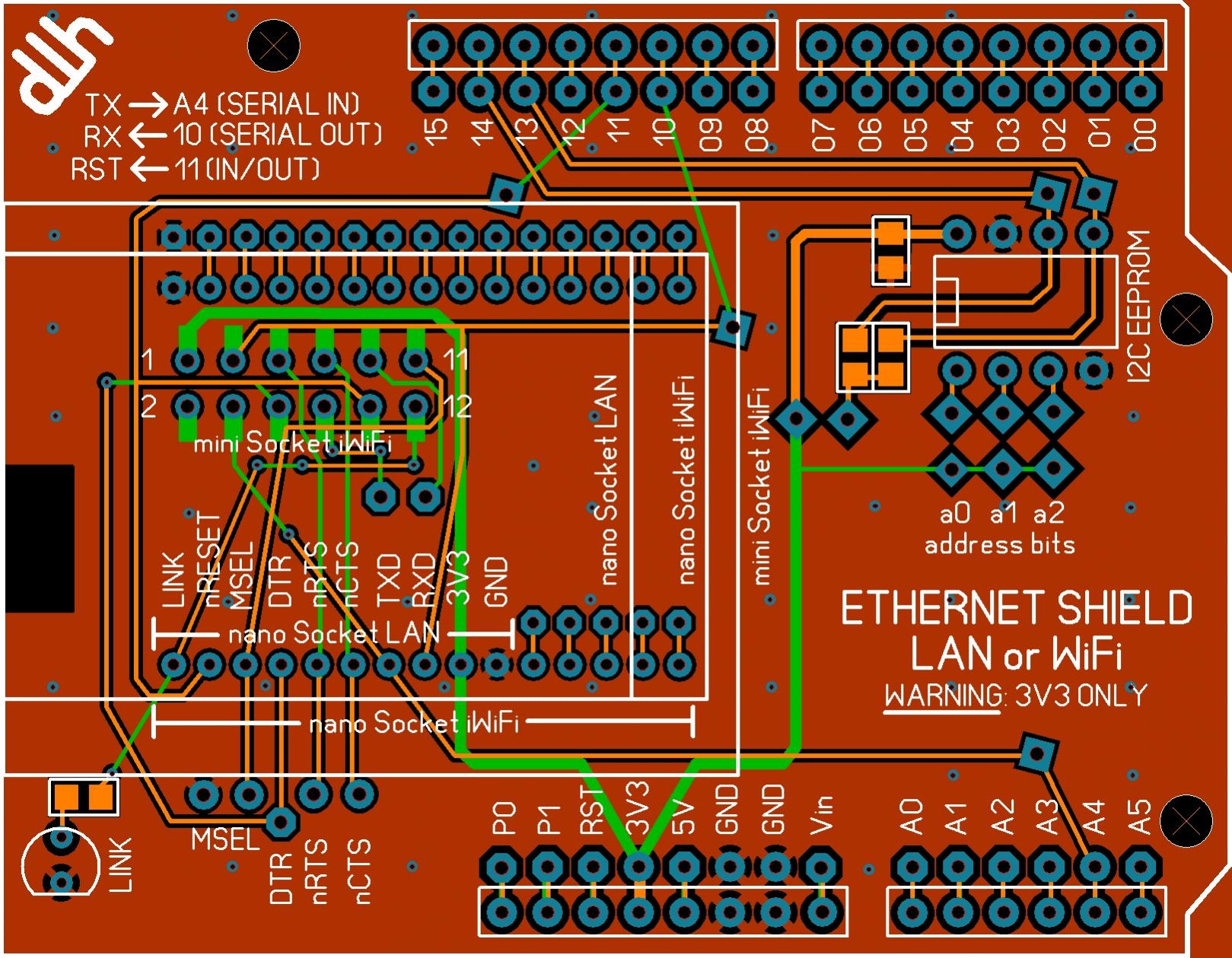
The diamond shaped pads are those that the user will likely need to solder in wire jumpers to make connections for pull-ups, set the address, etc.
The slightly askew square pads can be used to reroute the IO lines if needed. Cut the trace between pad and the sockets at the board edges and run a wire as needed.
The octagon pads are those which are unused for the hardware setup.
Round pads are in use by the hardware or hidden beneath the sockets.
I'm not sure how. If you mean for those who make their own boards, I think these will be available with all of the etching, etc. done and even with most of the SMT components preinstalled. The one I think you are referring to is for installing a jumper in case a pull-up is needed on the serial line - I just forgot the pull-up.
Last edited by dhouston; - 4th June 2011 at 20:39.
I think this really is the final version. It's been reviewed ab blessed by macrackit. I've asked ConnectOne to review it but haven't heard back, yet. This is an x-ray vision (top) view which makes it easier to follow the connections between features.
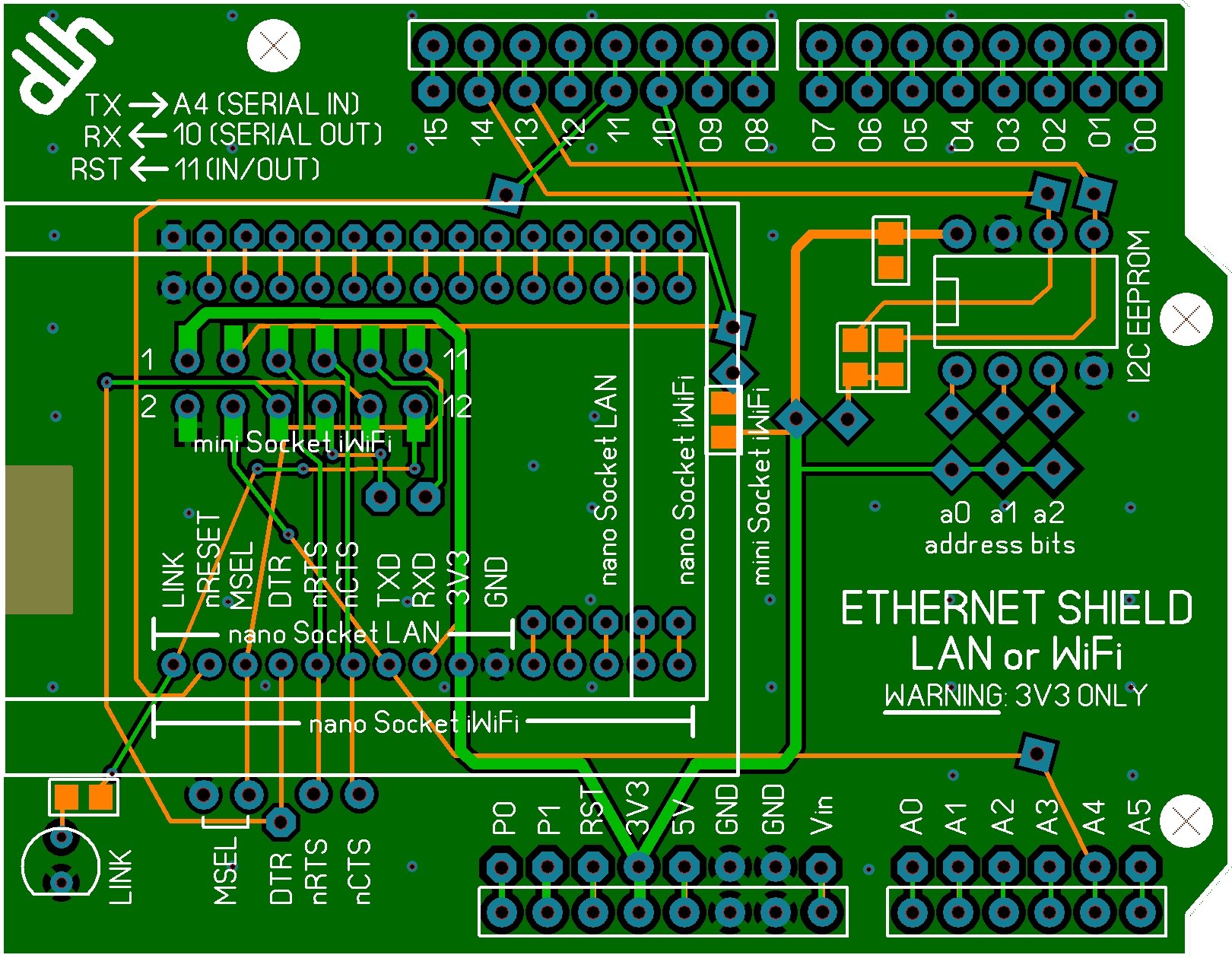
Last edited by ScaleRobotics; - 5th June 2011 at 06:58.
Hi Dave,
OK, but the bootloader does not hold up the UART once the main program starts to execute, you're free to use it as you wish then. But I guess you have your reasons, I just had to ask.
Am I right in that you have the SPI pins on the ConnectOne module connected to the MSSP module on the AMICUS18 so that it can use that interface instead of the bit-banged serial? Never having used the device in question I don't know exactly how much information needs to passed betwteen the module and the microcontroler but bit-banged serial isn't directly fast. I'm guessing it's not that much since any web-content doesn't have to pass "thru" the PIC.
As for the disclaimer. I didn't take it as such and I have absolutely no problem with this, on the contrary, it's why we're here - to share ideas and learn from each other. But it should stays on topic for this forum, which I must admit I sometimes think it doesn't. If these shields can be used with other devices programmed in whatever language that's great but I think we should try keeping it on topic which is MELABS PBP, not ZBasic, BasicX, PICAXE, PROTON, MikroBASIC, C or anything else.
Keep it up!
/Henrik.
 Members who have read this thread : 0
You do not have permission to view the list of names.
 Posting Permissions

Bookmarks