

I'll finish the laying out connections after I get my XINO basic kit.
Now back to waiting for the long-promised Tibbo EM500/GA1000 firmware.


I'll finish the laying out connections after I get my XINO basic kit.
Now back to waiting for the long-promised Tibbo EM500/GA1000 firmware.
Last edited by ScaleRobotics; - 29th May 2011 at 16:58. Reason: sizing picture
Stll waiting for the long-promised Tibbo EM500/GA1000 firmware so I'm trying to fill the time productively. The ConnectOne shield now supports 2 WiFi and 1 NoFi module.
Oh, no! Now I'm also waiting for mackrackit to decide on an EEPROM and to start coding.
uhmm,
I need to quit falling asleep. I missed the part about volunteering..
I do not have a whole lot of time to dedicate to a new project as much as I want too. But I will try to find some time to play
As far as EEPROMs... FRAM seems kind of expensive. Not sure how big of one would be needed, maybe a 24FC1025 would be "OK" ? After it is all setup should be just READS....
Need to sleep on it some more
Dave
Always wear safety glasses while programming.
I already have board designs for a battery backed RTC and for an EEPROM. Both are I2C and they might be plugins on shields that should require one or the other. I use 64KB in another application so it would be simplest to just use it, as is. Or, it might be best to just provide for a DIP that the user could add.Originally Posted by mackrackit

I'm also kicking around my own design for a slightly more costly but much easier and much more powerful Arduino clone that would make a great test bed and development system It's all this time on my idle hands...
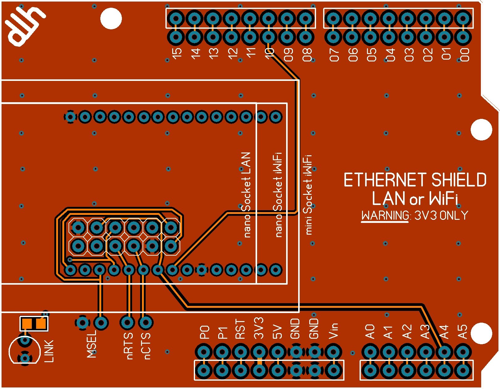
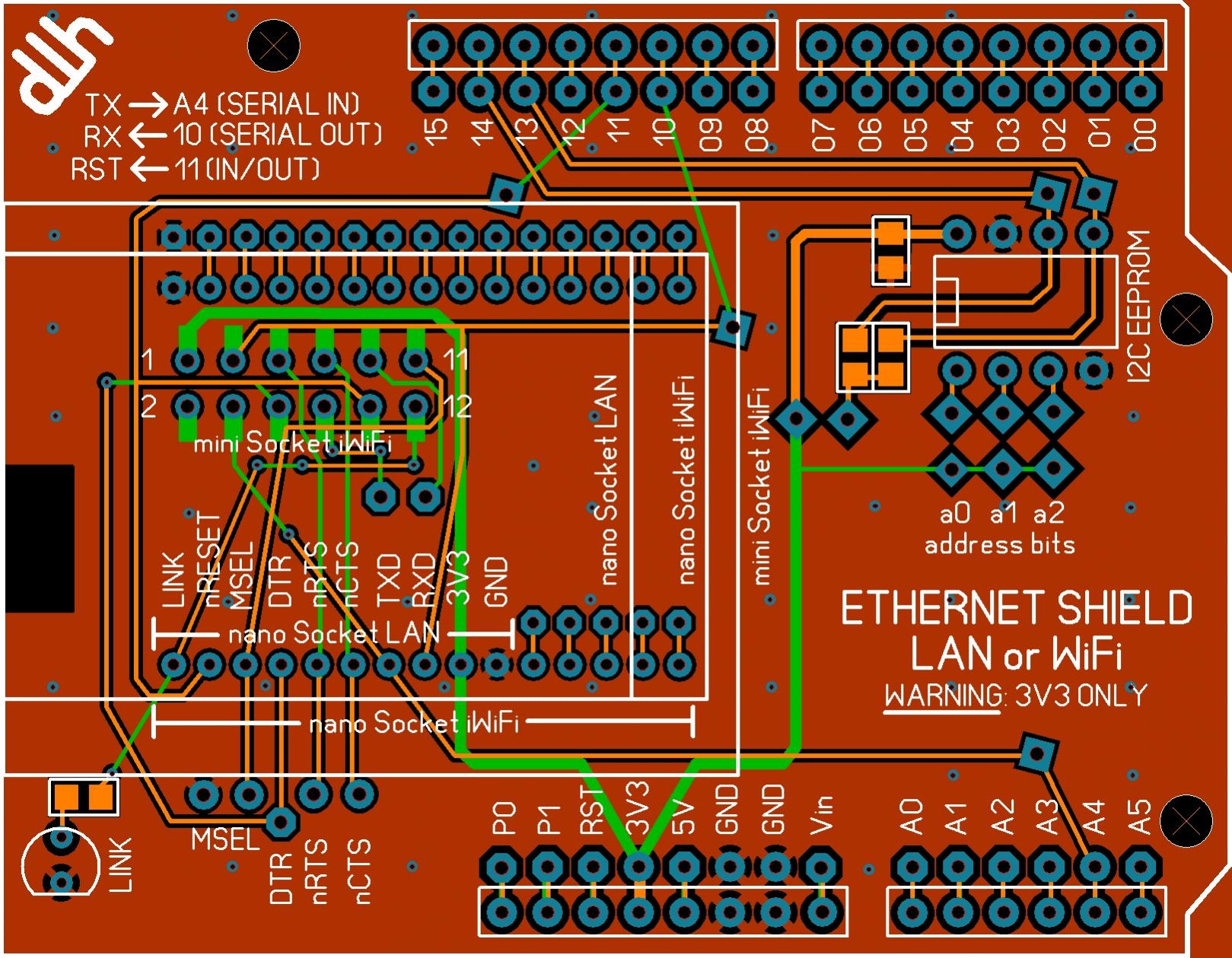
I think I can forget about seeing the Tibbo firmware anytime soon so here is what I think is the final layout for the ConnectOne ethernet shield. The TX, RX connections are dictated by the PICAXE and Xino. I still need to check this with the Xino designer but I think it's ready to have CircuitMart make some prototype PCBs.
When the Tibbo firmware is released I hope someone will consult a medium and let me know.
I'm going to spend my time finalizing the design of yet another Arduino clone. This will use a ZBasic ZX328n but it will be socketed so it can be replaced with a AVR Mega328P.
When my Xino kit arrives I'll see whether it is practical to modify to use the comparators as inverters for TX, RX. That should work with 16F88, 16F886/887 and 18P25K20/22, lowering the chip count.

Ask your supplier to let you know
Steve
It's not a bug, it's a random feature.
There's no problem, only learning opportunities.
I must have missed something ..
Where/when did a picaxe come in and why???
Dave
Always wear safety glasses while programming.
Sleeping again, huh?
The Xino basic Arduino form factor main board was designed to be a super low cost way for educators to make use of the myriad of shields available. It can use 18-pin or 28-pin PICAXE or PIC. I have a kit en route and hope to modify it to add series resistors in the TX, RX lines so that the comparators in the 16F88, 16F886/887 & 18F25K20/22 can be configured as inverters for TX, RX further reducing the parts count. There are pinouts for both 18-pin and 28-pin PICAXE chips at the above link.
I am not really familiar with PICAXE but it appears the software UART pins are predefined so that's why I connected them per the pinouts. Also, the newer PICAXE 18M2 and 28X2 chips are custom made by Microchip for PICAXE. I have no idea whether this just means they have their logo printed on them or whether there are changes to the designs. I haven't seen datasheets for them. But, if they can justify custom chips from Microchip, PICAXE must be very popular.
Since all the PBP software UART pins can be defined at compile time by the user, this should not be problem for PBP users.
And, I still have to study the pinouts to see where the I2C connections need to be made. I2C presents one problem in that there's no way to easily deal with address conflicts should another shield also use I2C. I'll probably just tie all the address pins high with the leads exposed in such a way that the user can cut PCB traces to change the address. Also, multiple pull-ups could be problematic
Also, I already have small I2C boards with 64KB EEPROM (SMT) which could be an optional item. I also have a similar board with a battery-backed RTC which uses the same pinout . But, I don't want to become a supplier (My next change of address may make me inaccessible.) so I'll have to see if the Xino folks will make them. Still, it might be best just to design for a DIP-8 socket and through-hole pull-ups.
Last edited by dhouston; - 31st May 2011 at 13:02.
I just noticed that the Xino Pro, which uses the same pin arrangements, has a pinout for the 18F25K20 on its web page. That should help in determining which PICs are compatible.
What about jumpers? Add a little to the cost but it might be worth it in the long run.I2C presents one problem in that there's no way to easily deal with address conflicts should another shield also use I2C. I'll probably just tie all the address pins high with the leads exposed in such a way that the user can cut PCB traces to change the address.
Dave
Always wear safety glasses while programming.

or how about solder jumpers? No added cost at all.
-Bert
The glass is not half full or half empty, Its twice as big as needed for the job!
http://foamcasualty.com/ - Warbird R/C scratch building with foam!

The wait is over
http://blog.tibbo.com/
The new firmware was updated yesterday.
Regards
Ian
I've done a bit of both and also added through-hole pads to each of the five interface lines so they can be rerouted by cutting traces and adding wires.
One remaining issue - the socket for the mini iWiFi is taller than those for the other two modules.It's not a problem for end users but is for testing. I guess I'll have to find people with each who are willing to test and maybe write a short tutorial in exchange for one of the prototype boards.
Last edited by dhouston; - 31st May 2011 at 15:45.
Thanks.
Now I'm patiently awaiting the documentation and newsletter.
Perhaps. The time between laboratory and release with documentation varies from a few days to a few years. The product manager told me they had it working about 10 days ago so nothing is really new. I'll go back to patiently waiting.
Their web site has said for the other long supported EMxxxx modules that the 5 interface lines are (in essence) programmable. I just need confirmation that this is also the case for EM500.The module utilizes SPI interace and only requires five I/O line to control. Flexible mapping allows your application to use any five available I/O pins.
Last edited by dhouston; - 31st May 2011 at 17:14.
OK. I found the new firmware and documentation for the Tibbo. As soon as I'm satisfied with the details I'll get the prototype ethernet shield PCBs on order. They should be here within 2 weeks.
I can do the Tibbo testing. For ConnectOne, I have a nano LanReach but would have to solder headers to it to turn it into a nano SocketLan. I would rather not do that so I need volunteers to test all three ConnectOne modules. I'll give the volunteers an unpopulated PCB and maybe I'll install the SMT resistors and caps as I have those on hand. I cannot supply the rest.
I have a iL-SM2144N1-I with headers.
Something looks wrong on your board or maybe I have the wrong part or.... is the top view the bottom of the top view?
Dave
Always wear safety glasses while programming.
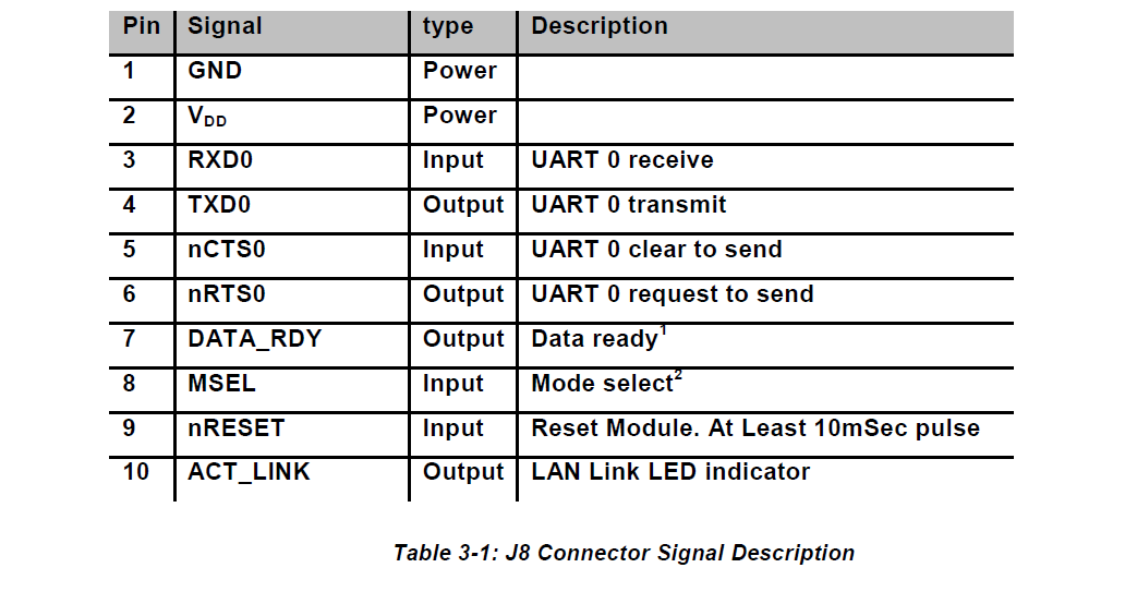
I think Mouser has the PNs confused. I have this one and I think you have this one. The only difference is one has headers and one does not and the one with headers does not have the teensy-weensy humanoid-unfriendly connector shown in Fig. 3-1-1 of the datasheet (p4-1) for ours.
I've been working off the drawings in the datasheets so I think things are OK but I have been jumping back and forth between the two shields as well as two other projects. I'll print out a life-size copy of the .PNG and see if things fit. What, specifically, looks wrong? It mounts in the 10 leftmost holes of the two 15-pin sockets (the nano Socket iWiFi uses all 30 & the iWiFi uses the 2x6x100 socket) with the RJ45 to the left. (Spark Fun has 10-pin and 5-pin 2mm sockets which I hope will work end-to-end for the 30-pinner. They will mail small shipments, saving cost.)
Last edited by dhouston; - 1st June 2011 at 11:41.
I now have the Edit function back but with a 10-minute limit which is too short for slow, dim-witted geezers. At least I no longer am pestered by the random phrases - any semi-intelligent bot would quickly figure out there were only 5-6 answers, anyway.
The actual connections for our modules are shown in this post. That is part of another, much larger project. The other project taking up most of my time is shown here.
The ones I have been using have the 30 pin molex on the bottom and have been coming with the two ten pin headers on the sides installed. I also purchased 2mm headers that I have not used yet. Maybe the next batch will need them...
The thing that looks wrong, and it is probably the way I am looking at the drawing. When looking down my module with the RJ45 to the right, the serial pins are on the upper header, J7. To me it looks like your drawings show a view from the bottom of both layers. Putting the RJ45 over the EEPROM...
Dave
Always wear safety glasses while programming.
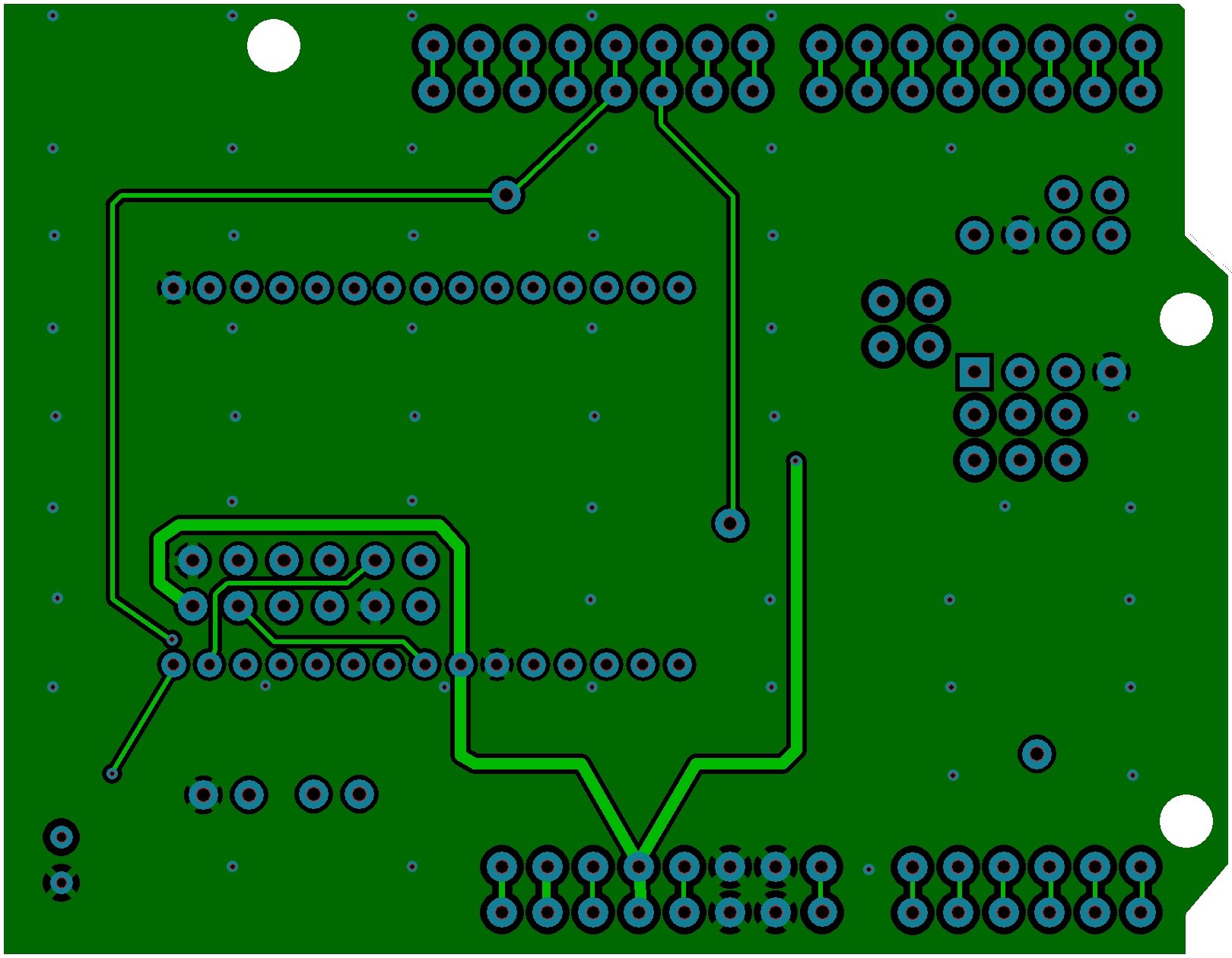
That's possible - I was using the pinouts from the data sheets and they may be top views when I was thinking the opposite (or vice versa). Try it with the RJ11 on the left, using the top (coppertone) view.
Here's the latest layout. Can you reduce the size the way scalerobotics was doing? If I do it in Paint Shop Pro, it loses too much detail.
Last edited by ScaleRobotics; - 1st June 2011 at 14:18. Reason: scaling
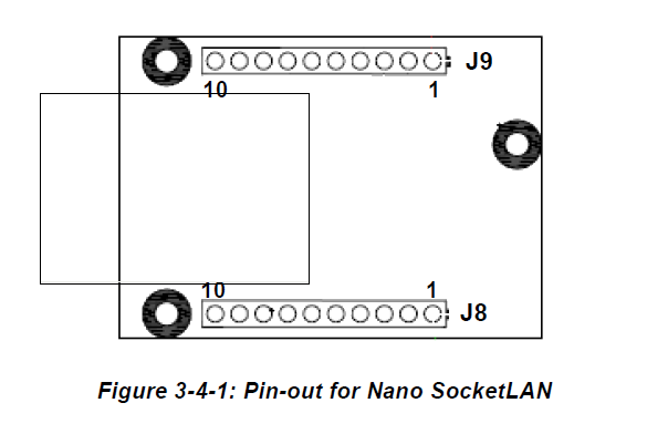
Below is the pinout from the data sheet with the drawing flipped over to give a top view and the outline of the RJ45 added.
Dave,
Does your data sheet show J8, pins 1-4 being VDD, VSS, RX, and TX (I may have the order off but those are the four pins used on the module I have)
Thanks Walter for scaling.
Dave
Always wear safety glasses while programming.
I'm using this datasheet. A tech at ConnectOne told me the pinout was the same on my pinless version.
I have changed the arrows on the silkscreen to reflect signal direction. That may help.
RX <- 10 (Serial Out)
TX -> A4 (Serial In)
RST <- 11 (In/Out)
Doh... I thought I was awake, guess I was not.
I see everything now except J8 PIN 1. GND connection.
Dave
Always wear safety glasses while programming.
Right click the JPG, View Image, then magnify. The GNDs are all just thermal pads that connect to the ground plane which covers both surfaces.
Hmmm,
Now I can see it...

Dave
Always wear safety glasses while programming.
I should have had you look at the others. I think the mini Socket iWiFi is upside down, backwards and, maybe, inside out. I'll try to straighten it out and double check the others tomorrow after getting a bit of rest. I've been putting in more time than is good for a geezer.
I think this fixes the problem with the mini Docket iWiFi being upside down, backwards and inside out. The Connect One drawings in the datasheet do not identify whether the views are top or bottom and some even complicate things further by showing topside components on what is a bottom view drawing.
I would appreciate it if those of you who are interested in these shields would download the Connect One datasheets and double-check my work. These all start to look alike after 2-3 days.
Here is the list of connections for the mini Socket iWiFi with my modified pinout drawing that presents a top view.
There is a mistake in the above drawing - pin 1 should be on the left. I caught it in the layout but forgot to fix the drawing.
Last edited by dhouston; - 2nd June 2011 at 05:12.
I will try to get a chance to study them in the next day or so. Got a client with a problem... luckily it is not on one of my systems
Dave
Always wear safety glasses while programming.
PM me with your email and I'll email the line drawings I made. You can check them against the datasheets and, if they jibe, check them against the layout .PNGs
I have offered the Gerbers to Connect One in exchange for their reviewing the layout. Stay tuned.
Last edited by dhouston; - 3rd June 2011 at 18:26.

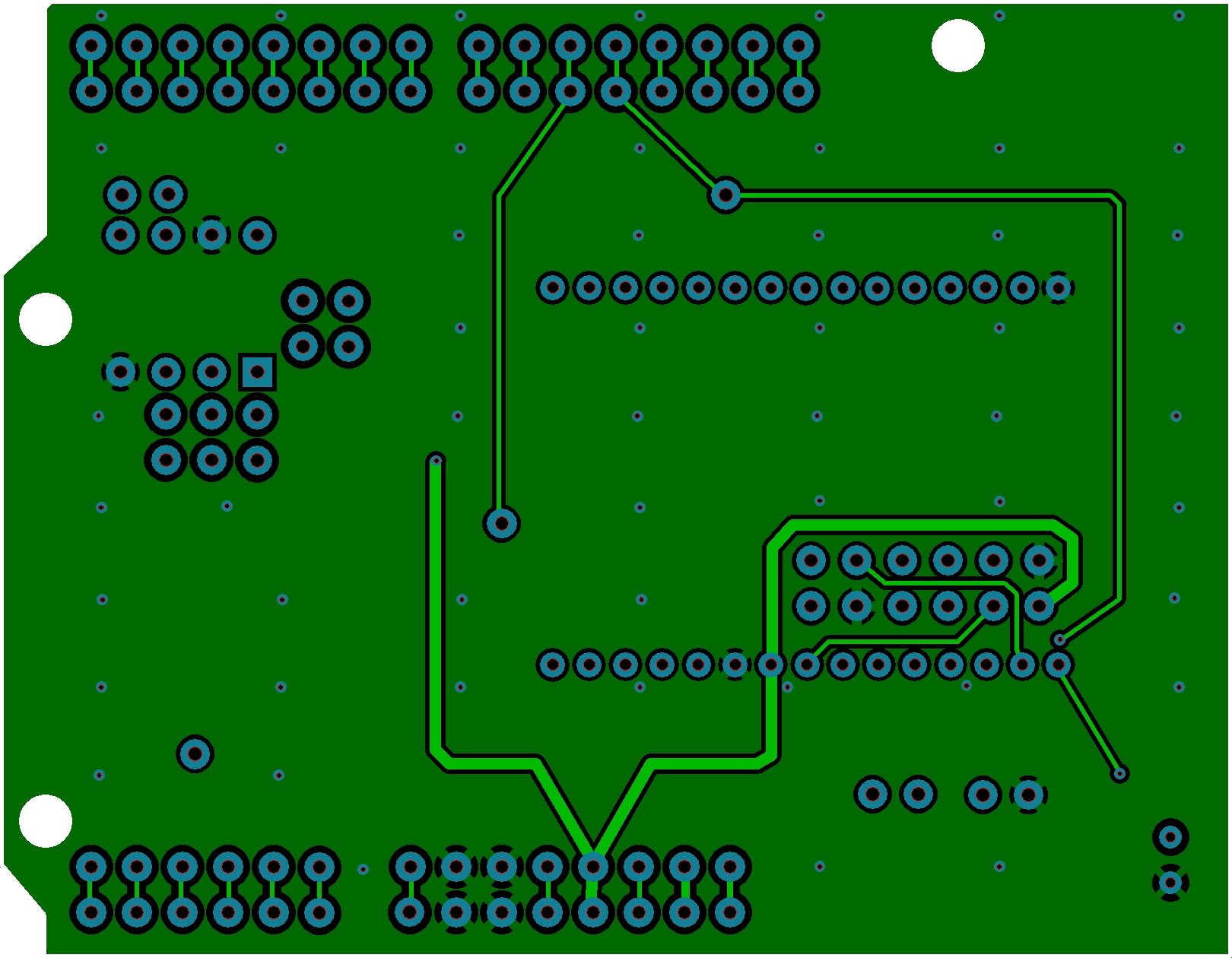
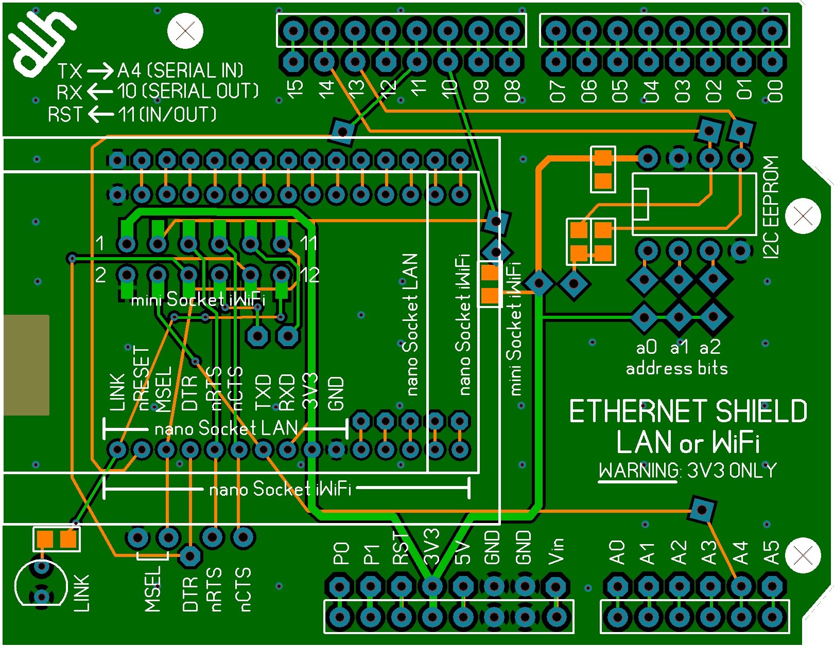
Why the offset square pads?
Why not place them at right angles, or make them round?
The one on the left above the I2C eeprom looks like a recipe for disaster (from a home-brewed PCB perspective).
Hi,
I had decided not to stick my nose into this but I'm going to anyway....
What are the reasons for not using the USART pins but instead using some ordinary I/O pins for serial in and out? The USARTs RX and TX pins are on 00 and 01 on the AMICUS18 which is what this forum section is about. Taking a quick look at the XINO Basic it TOO lists pins 00 and 01 as the USART RX and TX pins when used with the PICAXE chips listed there.
The PICAXE28X2 is just an 18F25K22 with some firmware so it TOO has the USART pins on RC6 and RC7 which then connects to pins 0 and 1. The AMICUS18 uses the 25K20 which also have the USART on RC6 and RC7.
Are these devices (nanoSocketLAN) not meant to be connected directly to a microcontroler with an USART thus expecting "true" data? Is the reason for not using the USART that they expect inverted data (I can't imagine that) and therfor you are using plain I/O and bit-banged serial where the polarity can be inverted instead of the microcontrolers onbaord USART?
I know you're providing pads so it can be re-wired but there must be a very specific reason for not wiring RX and TX to microcontrolers USART where they belong.
/Henrik.
The ConnectOne uses TRUE mode.
I like to leave the USART open for interruptible input to the MCU.
Dave
Always wear safety glasses while programming.
It's mostly because the various bootloaders are coded to use the hardware USART. And, I tend to think of these as development systems for READ (Rapid Embedded Application Development) where there will be a lot of changes, trials, errors, etc. rather than as finished products that stand on their own although they can certainly be used that way, as well.
DISCLAIMER: This thread and the Tibbo thread were not intended to disparage your WizNET approach. I'm just of the opinion that most folk are as lazy as me and use various Basic dialects so they don't have to learn ASM, C, etc. In that vein, both the ConnectOne and Tibbo modules do most of the heavy lifting that you're doing with SPI in your thread, making life easier for those of us inclined to take the easy way out. The Tibbo module requires coding but it's all in another Basic dialect and gets loaded as firmware into the Tibbo module rather than using much code space in the MCU be it PIC, PICAXE, Arduino AVR, or ZBasic AVR. And, it was fairly easy to design the shields so all the various modules (except for the 4 Mb flash) are plug-ins - no soldering required (I suspect the Tibbo & ConnectOne shields will have the SMT components preinstalled.)
The diamond shaped pads are those that the user will likely need to solder in wire jumpers to make connections for pull-ups, set the address, etc.
The slightly askew square pads can be used to reroute the IO lines if needed. Cut the trace between pad and the sockets at the board edges and run a wire as needed.
The octagon pads are those which are unused for the hardware setup.
Round pads are in use by the hardware or hidden beneath the sockets.
I'm not sure how. If you mean for those who make their own boards, I think these will be available with all of the etching, etc. done and even with most of the SMT components preinstalled. The one I think you are referring to is for installing a jumper in case a pull-up is needed on the serial line - I just forgot the pull-up.
Last edited by dhouston; - 4th June 2011 at 20:39.
I think this really is the final version. It's been reviewed ab blessed by macrackit. I've asked ConnectOne to review it but haven't heard back, yet. This is an x-ray vision (top) view which makes it easier to follow the connections between features.
Last edited by ScaleRobotics; - 5th June 2011 at 06:58.
Hi Dave,
OK, but the bootloader does not hold up the UART once the main program starts to execute, you're free to use it as you wish then. But I guess you have your reasons, I just had to ask.
Am I right in that you have the SPI pins on the ConnectOne module connected to the MSSP module on the AMICUS18 so that it can use that interface instead of the bit-banged serial? Never having used the device in question I don't know exactly how much information needs to passed betwteen the module and the microcontroler but bit-banged serial isn't directly fast. I'm guessing it's not that much since any web-content doesn't have to pass "thru" the PIC.
As for the disclaimer. I didn't take it as such and I have absolutely no problem with this, on the contrary, it's why we're here - to share ideas and learn from each other. But it should stays on topic for this forum, which I must admit I sometimes think it doesn't. If these shields can be used with other devices programmed in whatever language that's great but I think we should try keeping it on topic which is MELABS PBP, not ZBasic, BasicX, PICAXE, PROTON, MikroBASIC, C or anything else.
Keep it up!
/Henrik.
 Members who have read this thread : 0
You do not have permission to view the list of names.
 Posting Permissions

")
Bookmarks