


hy everyone i am a new user here...
i have a project and i need some help plz
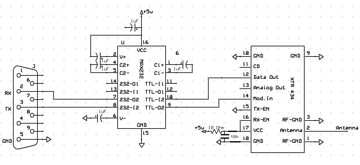
i am using the aurel transceiver xtr434 and i am getting on the pin 12 data out a voltage of 2.45V whatever the input of the other transceiver is (0 or 5V)..
so if anyone has a shematic for how to connect this transceiver or if anyone faced this problem send me the reply plz..
thanks in advance
regards...


Bookmarks