


Can you solder a couple of wire onto your board?

Can you solder a couple of wire onto your board?
Dave
Always wear safety glasses while programming.
I finally got back to this.
To set the iChip up for you network change the below as needed. The config utility is not needed.
It may take a minute or two to get a connection and "blink".Code:TX VAR PORTC.0 'ICHIP PIN 8 RX VAR PORTC.1 'ICHIP PIN 7 PAUSE 2000 BOOT: 'iCHIP SET UP SEROUT2 TX,84,["AT+iBDRA",$d,$a] ' FORCE ICHIP TO AUTO BAUD SERIN2 RX ,84,2500,BOOT,[WAIT("I/OK")] ' SETTING BAUD TO 9600 PAUSE 100 SEROUT2 TX,84,["AT+iRPG=booger",$d ,$a] ' SETS REMOTE PASSWORD SERIN2 RX ,84,2500,BOOT,[WAIT("I/OK")] PAUSE 100 SEROUT2 TX,84,["AT+iWSEC=0",$d ,$a] ' WPA-TKIP PROTOCAL SERIN2 RX ,84,2500,BOOT,[WAIT("I/OK")] PAUSE 100 SEROUT2 TX,84,["AT+iWLSI=MACLAN2",$d,$a]' SET SSID WE ARE LOOKING FOR SERIN2 RX ,84,2500,BOOT,[WAIT("I/OK")] ' PAUSE 100 SEROUT2 TX,84,["AT+iWLPP=macmac3X3",$d,$a]' SET PASS-PHRASE SERIN2 RX ,84,2500,BOOT,[WAIT("I/OK")] PAUSE 100 SEROUT2 TX,84,["AT+i!RP10",$d,$a] ' REPORTS CONNECTION PARAMETERS SERIN2 RX ,84,2500,BOOT,[WAIT("I/OK")] ' FOR DEBUGGING PAUSE 100 SEROUT2 TX ,84,[ "AT+iIPA?" , $d , $a ] ' RETURNS IP ADDRESS PAUSE 100 ' FOR DEBUGGING SEROUT2 TX,84,["AT+iWWW",$d,$a] ' STARTS WEB SERVER SERIN2 RX,84,1000,BOOT,[WAIT("I/(")] PAUSE 100 GOSUB BLINK ' IF WE GET HERE BLINK PAUSE 100 GOTO BOOT
Then look at your router and find a new device address.
Enter the address into a browser
http://192.168.2.19/ichip
You should have the web config page.
Dave
Always wear safety glasses while programming.
aOriginally Posted by mackrackit

I think I know where you are going with this, Dave. Are you implying that if I solder 3 individual wires to the pins on my PCB that are TX, RX and GND and then connect those three wires to a DB-9 connector, I can jurry-rig a serial interface to my PCB?
I could do this if that is what you are implying, but I also have the problem that none of our computers have a serial interface on them....they are all newer computers and it seems that only older computers have RS-232. I supposed we could try to use a USB to RS-232 converter cable, but we have had very bad experience in trying to use those...they typically don't work well with serial applications.
John
Does this code actually work with one of your ConnectOne MiniSockets?
I will try this with mine. If it works with yours and not with mine, this may be a way I can verify whether my module has gone bad or not...which is unforunately one of my increasing suspicions.
John
The code was tested on a ConnectOne Nano Socket. Same chipset as far as I know.
Yup, I am implying bugging in a DB9.
I used one of these while debugging the above code on a win7 netbook.But I agree, the converters are not good for everything and I have brands that do not work at all.
Or you could get a LCD with a serial back-pack to see what is going on. Either way, it will sure make debugging faster.
Dave
Always wear safety glasses while programming.
I modified your proven code you inserted above very slightly per below. Because my PCB has the _RES_PD and MSEL interfaces connected to MCU pins for control of the module, I had to insert the "Initialize" statements for those interfaces per programmers manual to supposedly have module in normal AT+i ops for the internal serial interface. I also inserted some WRITE to EEPROM statements with comments and some LED blinking to assist my troubleshooting.
As you can see from the comments, I never get the first I/OK acknowledgment from the module, which tells me that the internal serial interface from my MCU to the module is not working.
Next step I guess is to solder 3 wires to my PCB to provision a temporary serial interface to my PC to see if Serial interface is working from MCU. Any other suggestions?
Code:'< FL_PIC16F886 >' ' First valid PIC found within the first 200 lines will ' highlight AND set device. '< FL_PBPW >' ' OR < FL_PBPL > '< FL_MPASM >' ' OR < FL_PM > ' Set configuration fuses for the MCU ' To use standard config include file, comment out below statement @ __config _CONFIG1, _HS_OSC & _WDT_OFF & _MCLRE_OFF & _LVP_OFF & _CP_OFF ASM ERRORLEVEL -306 ENDASM DEFINE OSC 8 ADCON1 = %00001110 ' Define variables and aliases CNT VAR BYTE CNT = 0 temp VAR BYTE 'Already declared in main program as temp D_LAY VAR BYTE ADR VAR BYTE [9] MSEL VAR PORTC.1 ' iChip Mode Select (MSEL) _RES_PD VAR PORTC.2 ' iCHIP RESET/Power-Down (_RES_PD) TX VAR PORTC.6 RX VAR PORTC.7 PAUSE 2000 'Initialize iWiFi MiniSocket Module HIGH _RES_PD ' Set high for normal ops PAUSE 500 ' Delay to stabilize coming out of power down mode LOW MSEL ' Exit SERIALNET mode and return iChip to normal AT+i mode PAUSE 10000 ' Delay 10 sec HIGH MSEL ' Proceed with normal ops PAUSE 2000 ' Delay 2 sec BOOT: 'iCHIP SET UP HIGH PORTC.4 :PAUSE 500 ' Short Blink the LED_RED as heart beat LOW PORTC.4: PAUSE 500 WRITE 3,3 'EEPROM test to see if program executes to here..it does. SEROUT2 TX,84,["AT+iBDRA",$d,$a] ' FORCE ICHIP TO AUTO BAUD WRITE 4,4 'EEPROM test to see if program executes to here..it does. SERIN2 RX ,84,2500,BOOT,[WAIT("I/OK")] ' SETTING BAUD TO 9600 PAUSE 100 WRITE 5,5 'EEPROM test to see if program executes to here..IT DOESN'T! ' It just keeps looping to BOOT and blinking LED_RED SEROUT2 TX,84,["AT+iRPG=booger",$d ,$a] ' SETS REMOTE PASSWORD SERIN2 RX ,84,2500,BOOT,[WAIT("I/OK")] PAUSE 100 'SEROUT2 TX,84,["AT+iWSEC=0",$d ,$a] ' WPA-TKIP PROTOCAL 'SERIN2 RX ,84,2500,BOOT,[WAIT("I/OK")] PAUSE 100 SEROUT2 TX,84,["AT+iWLSI=Buckskin",$d,$a]' SET SSID WE ARE LOOKING FOR SERIN2 RX ,84,2500,BOOT,[WAIT("I/OK")] ' PAUSE 100 'SEROUT2 TX,84,["AT+iWLPP=macmac3X3",$d,$a]' SET PASS-PHRASE 'SERIN2 RX ,84,2500,BOOT,[WAIT("I/OK")] PAUSE 100 SEROUT2 TX,84,["AT+i!RP10",$d,$a] ' REPORTS CONNECTION PARAMETERS SERIN2 RX ,84,2500,BOOT,[WAIT("I/OK")] ' FOR DEBUGGING PAUSE 100 SEROUT2 TX ,84,[ "AT+iIPA?" , $d , $a ] ' RETURNS IP ADDRESS PAUSE 100 ' FOR DEBUGGING SEROUT2 TX,84,["AT+iWWW",$d,$a] ' STARTS WEB SERVER SERIN2 RX,84,1000,BOOT,[WAIT("I/(")] PAUSE 100 GOSUB Blink ' IF WE GET HERE BLINK LED_GRN PAUSE 100 GOTO BOOT Blink: HIGH PORTC.5 :PAUSE 500 ' Short Blink the LED_GRN..NEVER GETS HERE! LOW PORTC.5: PAUSE 500 RETURN
Last edited by jellis00; - 15th October 2011 at 22:35.
The only pins used for normal operation are the GND, VDD, RXD0, and TXD0. All others are left floating.
You are keeping things in reset by playing with the other pins.
Dave
Always wear safety glasses while programming.
I understand your point, Dave, but I already built the PCB with hookups to MSEL and _RES_PD from the MCU so have to make them work in the setup.
This code works! The fix was to set TRISC so that _RES_PD and MSEL were declared as outputs. When this worked I was able to read the EEPROM to see what the IP was for the iChip website that it established and then to got to it via http://xx.xx.x.xxx/ichip and set the parameters I wanted.
Now on to figure out how to integrate this working code into my application so I can use the iWiFi module to send an email via its connection with my wireless router to the internet.
Thanks for your help, Dave. I hope this attached code will show others who visit this thread how to setup a iWiFi MiniSocket module to set its parameters without having to use the config utility.
/s/ John Ellis
Code:' STATUS: Works OK! '< FL_PIC16F886 >' ' First valid PIC found within the first 200 lines will ' highlight AND set device. '< FL_PBPW >' ' OR < FL_PBPL > '< FL_MPASM >' ' OR < FL_PM > ' Set configuration fuses for the MCU ' To use standard config include file, comment out below statement @ __config _CONFIG1, _HS_OSC & _WDT_OFF & _MCLRE_OFF & _LVP_OFF & _CP_OFF ASM ERRORLEVEL -306 ENDASM DEFINE OSC 8 ADCON1 = %00001110 TRISC.1 = 0 ' Make pin output for MSEL TRISC.2 = 0 ' Make pin output for _RES_PD ' Define variables and aliases CNT VAR BYTE CNT = 0 temp VAR BYTE 'Already declared in main program as temp D_LAY VAR BYTE ADR VAR BYTE [9] MSEL VAR PORTC.1 ' iChip Mode Select (MSEL) _RES_PD VAR PORTC.2 ' iCHIP RESET/Power-Down (_RES_PD) TX VAR PORTC.6 RX VAR PORTC.7 PAUSE 2000 'Initialize iWiFi MiniSocket Module HIGH _RES_PD ' Set high for normal ops PAUSE 500 ' Delay to stabilize coming out of power down mode LOW MSEL ' Exit SERIALNET mode and return iChip to normal AT+i mode PAUSE 10000 ' Delay 10 sec HIGH MSEL ' Proceed with normal AT+i command ops PAUSE 2000 ' Delay 2 sec BOOT: 'iCHIP SET UP HIGH PORTC.4 :PAUSE 500 ' Short Blink the LED_RED as heart beat LOW PORTC.4: PAUSE 500 ' while disconnected from router. WRITE 3,3 'EEPROM test to see if program executes to here..it does. SEROUT2 TX,84,["AT+iBDRA",$d,$a] ' FORCE ICHIP TO AUTO BAUD WRITE 4,4 'EEPROM test to see if program executes to here..it does. SERIN2 RX ,84,2500,BOOT,[WAIT("I/OK")] ' SETTING BAUD TO 9600 PAUSE 100 WRITE 5,5 'EEPROM test to see if program executes to here..it does! SEROUT2 TX,84,["AT+iRPG=booger",$d ,$a] ' SETS REMOTE PASSWORD SERIN2 RX ,84,2500,BOOT,[WAIT("I/OK")] PAUSE 100 'SEROUT2 TX,84,["AT+iWSEC=0",$d ,$a] ' WPA-TKIP PROTOCAL ' Commented out until WPA setup on wireless router 'SERIN2 RX ,84,2500,BOOT,[WAIT("I/OK")] PAUSE 100 SEROUT2 TX,84,["AT+iWLSI=Buckskin",$d,$a]' SET SSID WE ARE LOOKING FOR SERIN2 RX ,84,2500,BOOT,[WAIT("I/OK")] ' PAUSE 100 'SEROUT2 TX,84,["AT+iWLPP=macmac3X3",$d,$a]' SET PASS-PHRASE ' Commented out until WPA setup on wireless router 'SERIN2 RX ,84,2500,BOOT,[WAIT("I/OK")] PAUSE 100 SEROUT2 TX,84,["AT+i!RP10",$d,$a] ' REPORTS CONNECTION PARAMETERS SERIN2 RX ,84,2500,BOOT,[WAIT("I/OK")] ' FOR DEBUGGING PAUSE 100 SEROUT2 TX ,84,[ "AT+iIPA?" , $d , $a ] ' RETURNS IP ADDRESS ' FOR DEBUGGING SERIN2 RX ,84 , 2500 ,BOOT , [ DEC ADR[0] , DEC ADR[1] , DEC ADR[2] , DEC ADR[3] ] PAUSE 100 WRITE 16,ADR[0] ' Write the IP to EEPROM for post run identify WRITE 17,ADR[1] WRITE 18,ADR[2] WRITE 19,ADR[3] WRITE 6,6 'EEPROM test to see if program executes to here..it does! SEROUT2 TX,84,["AT+iWWW",$d,$a] ' STARTS WEB SERVER SERIN2 RX,84,1000,BOOT,[WAIT("I/(")] PAUSE 100 GOSUB Blink ' IF WE GET HERE BLINK LED_GRN PAUSE 100 GOTO BOOT Blink: HIGH PORTC.5 :PAUSE 500 ' Short Blink the LED_GRN..IT DOES AFTER ~2 minutes! LOW PORTC.5: PAUSE 500 RETURN
Glad you got it working!!!
But,
TRISC.1 = 0 ' Make pin output for MSEL
TRISC.2 = 0 ' Make pin output for _RES_PD
Would/should not have made a difference because the HIGH/LOW commands do that in the background.
Must have been another change...
Dave
Always wear safety glasses while programming.
I thought it was working...and it is to a point. However I am seeing an anomaly I can't understand. I hope you can help me figure this out.
I am programming my application with the below code using a PICKIT2. I have the PICKIT2 set to "VDD Target" so that the PICKIT2 is not providing power...my application has its own power.
The programming of the device is normal and it starts working and executes the program normally as long as the PICKIT2 is still connected (but not providing power).
However, when I disconnect the PICKIT2 and power down my application and then reapply the application's power, the code is obviously stopping execution at the point in the code where the AT+i coommand is given to set auto-baud at 9600 baud. I know this from the WRITE 4,4 statement not appearing in EEPROM after the test run and the LED_RED not blinking. However, when I then reconnect the PICKIT2 and load the PICKIT2 software with its screen, my application then works normally and executes the complete program with the LED_RED blinking as a heart beat during the BOOT loop.
It is almost like the iWiFi module isn't getting power when the PICKIT2 is disconnected and therefore the AT+iBDRA fails...but it is getting power...I checked with a voltmeter.
I am stumped and can't go any further in integrating this code with my overall application until I resolve this anomaly.
Do you or anyone have any ideas why the iWiFi module would act this way with this code and this scenario?? At least I was able to use this code when it worked while PICKIT2 was connected to identify the IP address, log into the iChip web server from my PC via the wireless route,r and set parameters on the iChip.
John
CODE]
'< FL_PIC16F886 >' ' First valid PIC found within the first 200 lines will
' highlight AND set device.
'< FL_PBPW >'
'< FL_MPASM >'
' Set configuration fuses for the MCU
' To use standard config include file, comment out below statement
@ __config _CONFIG1, _HS_OSC & _WDT_OFF & _MCLRE_OFF & _LVP_OFF & _CP_OFF
ASM
ERRORLEVEL -306
ENDASM
DEFINE OSC 8
ADCON1 = %00001110
TRISC.1 = 0 ' Make pin output for MSEL
TRISC.2 = 0 ' Make pin output for _RES_PD
' Define variables and aliases
CNT VAR BYTE
CNT = 0
temp VAR BYTE 'Already declared in main program as temp
D_LAY VAR BYTE
ADR VAR BYTE [9]
MSEL VAR PORTC.1 ' iChip Mode Select (MSEL)
_RES_PD VAR PORTC.2 ' iCHIP RESET/Power-Down (_RES_PD)
TX VAR PORTC.6
RX VAR PORTC.7
PAUSE 2000
CLEAR
'Initialize iWiFi MiniSocket Module
HIGH _RES_PD ' Set high for normal ops
PAUSE 500 ' Delay to stabilize coming out of power down mode
LOW MSEL ' Exit SERIALNET mode and return iChip to normal AT+i mode
PAUSE 5000 ' Delay 5 sec
HIGH MSEL ' Proceed with normal AT+i command ops
PAUSE 2000 ' Delay 2 sec
BOOT: 'iCHIP SET UP
WRITE 3,3 'EEPROM test to see if program executes to here..it does under all conditions.
SEROUT2 TX,84,["AT+iBDRA",$d,$a] ' FORCE ICHIP TO AUTO BAUD
SERIN2 RX ,84,2500,BOOT,[WAIT("I/OK")] ' SETTING BAUD TO 9600
PAUSE 100
WRITE 4,4 'EEPROM test to see if program executes to here..it does when
'application is connected to PICKIT2 but DOESN'T when
'disconnected and then started on application's own power.
'However when reconnected to PICKIT2 and the PICKIT2 screen
'is then opened, it executes normally again. PICKIT2 is set to
'VDD target and is not supplying power to the application.
HIGH PORTC.4 :PAUSE 500 ' Short Blink the LED_RED as heart beat
LOW PORTC.4: PAUSE 500 ' during BOOT loop. Doesn't Blink when
' disconnected from PICKIT2!
SEROUT2 TX,84,["AT+iRPG=booger",$d ,$a] ' SETS REMOTE PASSWORD
SERIN2 RX ,84,2500,BOOT,[WAIT("I/OK")]
PAUSE 100
WRITE 5,5 'EEPROM test to see if program executes to here..it does!
'SEROUT2 TX,84,["AT+iWSEC=0",$d ,$a] ' WPA-TKIP PROTOCAL
' Commented out until WPA setup on wireless router
'SERIN2 RX ,84,2500,BOOT,[WAIT("I/OK")]
PAUSE 100
SEROUT2 TX,84,["AT+iWLSI=Buckskin",$d,$a]' SET SSID WE ARE LOOKING FOR
SERIN2 RX ,84,2500,BOOT,[WAIT("I/OK")] '
PAUSE 100
'SEROUT2 TX,84,["AT+iWLPP=macmac3X3",$d,$a]' SET PASS-PHRASE
' Commented out until WPA setup on wireless router
'SERIN2 RX ,84,2500,BOOT,[WAIT("I/OK")]
PAUSE 100
SEROUT2 TX,84,["AT+i!RP10",$d,$a] ' REPORTS CONNECTION PARAMETERS
SERIN2 RX ,84,2500,BOOT,[WAIT("I/OK")] ' FOR DEBUGGING
PAUSE 100
SEROUT2 TX ,84,[ "AT+iIPA?" , $d , $a ] ' RETURNS IP ADDRESS
' FOR DEBUGGING
SERIN2 RX ,84 , 2500 ,BOOT , [ DEC ADR[0] , DEC ADR[1] , DEC ADR[2] , DEC ADR[3] ]
PAUSE 100
WRITE 6,6 'EEPROM test to see if program executes to here..it does!
SEROUT2 TX,84,["AT+iWWW",$d,$a] ' STARTS iChip WEB SERVER
SERIN2 RX,84,1000,BOOT,[WAIT("I/(")]
WRITE 7,7 'EEPROM test to see if program executes to here..it does!
PAUSE 100
GOSUB Blink ' IF WE GET HERE BLINK LED_GRN
PAUSE 100
WRITE 16,ADR[0] ' Write the IP to EEPROM for post run identify
WRITE 17,ADR[1] ' Use PC host to then go to iChip web server at
WRITE 18,ADR[2] ' http:ADR[0].ADR[1].ADR[2].ADR[3] and set all
WRITE 19,ADR[3] ' desired iChip parameters for operations
GOTO BOOT
Blink:
HIGH PORTC.5 :PAUSE 500 ' Short Blink the LED_GRN..IT DOES AFTER ~1 minute!
LOW PORTC.5: PAUSE 500
RETURN
[/CODE]
Does the PIC run without the PicKit2?
Do a blinky to verify.
The Sparkfun device looks like it requires 5 and 3 volts.
Do you have both? Do they share a ground, VSS ?
Do you have capacitors near the PIC across VDD and VSS?
Did you change the backup battery problem?
Dave
Always wear safety glasses while programming.
I created a set of code that is the same as above post down through the _RES_PD and MSEL initialization followed only by a mainloop that blinks the LED. I did this so that all the setup code I was using was still the same in this test. This blinky code works whether the PICKIT2 is connected or not, so that didn't ID the problem.
Yes. Actually I have the iWiFi module running on 3.32 volts which is within its required Vdd range, so the lov voltage side of the Sparkfun converter is at 3.32v.The Sparkfun device looks like it requires 5 and 3 volts.
Do you have both?
Yes, I created a large ground plane layer on the top layer of my PCB right below the iWiFi module's outline where it is mounted to the PCB and this ground plane is shared with the level converter, the PIC and the rest of the PCB circuit.Do they share a ground, VSS ?
Yes, I have a 10uf tantalum and a 0.1uf ceramic connected near Vdd on the PIC to the Vss.Do you have capacitors near the PIC across VDD and VSS?
Yes, after I cut the traces to the pull-ups and greenwired them to Vcc I then replaced the backup battery and the clock is running fine and maintaining time.Did you change the backup battery problem?
These were all good questions and I appreciate you making me think through this. The bad news is that the code still quits running when the PICKIT2 is disconnected. However the good news is that I am now sending and receiving an email from the ichip (but only when the PICKIT2 is connected). Still trying to figure out the AT+i commands and right sequence of WAITs to only send one email when I want to. At this time for some reason it is sending two emails one minute apart repeated every 8 minutes. I thought I had the timing in this code set to only send one every 5 minutes and don't see where this is causing the repeats at the wrong interval. I only want it to send one every 5 minutes. I don't think I have the WAIT statements for I/OK, I/DONE, and I/ERROR correct and the timeouts to the EMAIL label may be causing repeated emails. Here is the EMAIL routine code I am using....any suggestions?
Code:EMAIL_SET: SEROUT2 TX,84,["AT+iSBJ:iChip ADC TEMPERATURE",$d,$a] 'Permanently sets Email header Subject field SERIN2 RX ,84,2500,EMAIL_SET,[WAIT("I/OK")] SEROUT2 TX,84,["AT+iTOA:[email protected]",$d,$a] 'Permanently sets Email addressee SERIN2 RX ,84,2500,EMAIL_SET,[WAIT("I/OK")] SEROUT2 TX,84,["AT+ito:jellis00",$d,$a] 'Permanently sets Email header =To: description SERIN2 RX ,84,2500,EMAIL_SET,[WAIT("I/OK")] SEROUT2 TX,84,["AT+iREA:[email protected]",$d,$a] 'Permanently sets the RETURN EMAIL Address SERIN2 RX ,84,2500,EMAIL_SET,[WAIT("I/OK")] SEROUT2 TX,84,["AT+iFRM:iChip",$d,$a] 'Permanently sets Email header =From: description. SERIN2 RX ,84,2500,EMAIL_SET,[WAIT("I/OK")] SEROUT2 TX,84,["AT+iSMTP:smtp.comcast.net",$d,$a]'Sets the SMTP Server Name or IP. SERIN2 RX ,84,2500,EMAIL_SET,[WAIT("I/OK")] SEROUT2 TX,84,["AT+iSMA=1",$d,$a] 'Permanently sets SMTP authentication method SERIN2 RX ,84,2500,EMAIL_SET,[WAIT("I/OK")] SEROUT2 TX,84,["AT+iSMP:Kevin111",$d,$a] 'Permanently sets authenticated SMTP login SERIN2 RX ,84,2500,EMAIL_SET,[WAIT("I/OK")] SEROUT2 TX,84,["AT+iSMU:je.lodestar",$d,$a] 'Permanently sets Authenticated SMTP login User Name. SERIN2 RX ,84,2500,EMAIL_SET,[WAIT("I/OK")] GOSUB Blink_GRN ' Short blink the LED_GRN if gets to here CNT = CNT + 1 FOR D_LAY = 1 TO 12 ' Delay for 1 min PAUSE 5000 NEXT D_LAY IF CNT > 4 THEN ' Execute if 5 minutes have passed FOR I = 0 TO 1 ' Long Blink LED_GRN 2x if gets to here HIGH PORTC.5 PAUSE 2000 LOW PORTC.5 PAUSE 2000 NEXT GOSUB GET_T GOSUB EMAIL ' Send an email every 2 minutes CNT = 0 ' Reset CNT after 2 minutes ENDIF PAUSE 2000 GOTO BOOT END ' To protect code from going to never-never-land EMAIL: SEROUT2 TX,84,["AT+iEMA:",$d,$a] 'Defines a plain text e-mail body SEROUT2 TX,84,["HI, THIS IS FROM 206 N Veterans.",$d,$a] SEROUT2 TX,84,["SENT EVERY HOUR.",$d,$a] SEROUT2 TX,84,["THE TEMPERATURE IS.",$d,$a] SEROUT2 TX,84,[DEC temp," F Inside.",$d,$a] SEROUT2 TX,84,["GO TO:",$d,$a] SEROUT2 TX,84,["http://www.lodestarassoc.com/ichip/ichip.html",$d,$a] SEROUT2 TX,84,["FOR A ONE MINUTE UPDATE.",$d,$a] SEROUT2 TX,84,[$d,$a,".",$d,$a] SERIN2 RX ,84,2500,EMAIL,[WAIT("I/OK")] GOSUB Blink_GRN ' Short blink LED_GRN 3x GOSUB Blink_GRN GOSUB Blink_GRN PAUSE 1000 GOTO Sent SERIN2 RX ,84,2500,EMAIL,[WAIT("I/ERROR")] GOSUB Blink_RED ' Short blink LED_RED 3x GOSUB Blink_RED GOSUB Blink_RED PAUSE 1000 SERIN2 RX,84,2500,EMAIL,[WAIT("I/DONE")] PAUSE 2500 ' After successfully sending the e-mail, allow 2.5 seconds 'delay for iChip re-initialization following an Internet mode session. GOSUB Blink_GRN ' Short blink LED_GRN 4x GOSUB Blink_GRN GOSUB Blink_GRN GOSUB Blink_GRN PAUSE 1000 Sent: ' Label for GOTO after email is sent to skip other WAIT checks. RETURN
To have accurate timing you will need to interrupt base the routine. You can use the RTC for that.
Dave
Always wear safety glasses while programming.
Dave, I am already using a DS1337 RTC in my applicaton with intention of using an interrupt from it on periodic basis to take a temperature reading and to initiate emails via the wireless module per the code I am currently trouble shooting. You can see the schematic of all this in an email I sent to Darrel Taylor which I copied you on in which I enlisted his help to find out why it is only working when a PICKIT2 is plugged in. I also included you on an email to ConnectOne techsupport and one that was direct to you regarding how you terminated the _RES_PD and MSEL connections in your application. Did you get them??
I just saw them, got two.
I do not have the RES_PD or MSEL pins connected to anything, they are floating.
Cut some more traces.
Or if all else fails, skip the sparkfun part and test with the whole system running on ~3 volts.
Ain't prototyping fun
Dave
Always wear safety glasses while programming.
Dave, I finally got it all working...or I should say almost all. Still troubleshooting one statement I want to add to the FTP process that is posting the wrong HH:MM values used from the RTC...for which I will describe and ask for help at end of this posting..
First of all, I made what I think are some good changes to the approach which I will share below for benefit of anyone else monitoring this thread that is trying to use the ConnectOne iWiFi MiniSocket module. I broke a lot of your sample code into some callable subroutines which I will list and explain below. I am posting all this code because I discovered that the ConnectOne programmers manual for the MiniSocket doesn't have any examples so it is somewhat difficult to get the syntax just right. Since these routines are tested and work it should save others from having this problem. Although I should say that the TechSupport people at ConnectOne have been very helpful and also say they are going to add examples to each command reference in their next publish of the programmers manual for the very reason I pointed out to them.
You will see a lot of WRITE to EEPROM statements embedded in this code which you can comment out or ignore...I use them to debug the AT+i command sequences so I know where the hangups are in the code by reading the EEPROM of the MCU after each run of the code when programming the MiniSocket module. I also have embedded a lot of variable duration, blinking LED statements to make use of a GREEN/ RED LED on my board to help see what is happening when the code is running.
From your mainloop when you want to use the MiniSocket module you first need to call this subroutine (BOOT) to initialize the module. You will have to substitue your own router SSID name in the iWLSI statement.
For completeness I will also list a couple of other routines that are called by BOOT (BROKE and DIP):Code:BOOT: 'Subroutine for setting up ConnectOne MiniSocket iWiFi module ' Blink Green LED 2x short at start of BOOT routine...for test only FOR I = 0 TO 1 HIGH LED_GRN PAUSE 250 LOW LED_GRN PAUSE 250 NEXT PAUSE 1000 'Initialize iWiFi MiniSocket Module HIGH _RES_PD ' Set high for normal ops PAUSE 500 ' Delay to stabilize if coming out of power up mode WRITE 48,2 'EEPROM test to see if program executes to here..it does. SEROUT2 TX,84,["AT+iBDRA",$d,$a] ' FORCE ICHIP TO AUTO BAUD SERIN2 RX ,84,2500,BOOT,[WAIT("I/OK")] ' SETTING BAUD TO 9600 PAUSE 100 WRITE 49,3 'EEPROM test to see if program executes to here..it does. SEROUT2 TX,84,["AT+iRPG=booger",$d ,$a] ' SETS REMOTE PASSWORD SERIN2 RX ,84,2500,BOOT,[WAIT("I/OK")] PAUSE 100 ' Commented out until WPA setup on wireless router 'SEROUT2 TX,84,["AT+iWSEC=0",$d ,$a] ' WPA-TKIP PROTOCAL 'SERIN2 RX ,84,2500,BOOT,[WAIT("I/OK")] PAUSE 100 WRITE 50,4 'EEPROM test to see if program executes to here..it does! SEROUT2 TX,84,["AT+iWLSI=EllisOfficeNetwork",$d,$a]' SET SSID WE ARE LOOKING FOR SERIN2 RX ,84,2500,BOOT,[WAIT("I/OK")] ' PAUSE 100 ' Commented out until WPA setup on wireless router 'SEROUT2 TX,84,["AT+iWLPP=passphrase",$d,$a] ' SET PASS-PHRASE 'SERIN2 RX ,84,2500,BOOT,[WAIT("I/OK")] 'PAUSE 100 WRITE 51,5 'EEPROM test to see if program executes to here..it does! SEROUT2 TX ,84, [ "AT+iIPA?" , $d , $a ] 'Report the current IP address SERIN2 RX ,84, 2500 ,BOOT , [ DEC ADR[0] , DEC ADR[1] , DEC ADR[2] , DEC ADR[3] ] 'Store IP in array WRITE 52,6 'EEPROM test to see if program executes to here..it does! GOSUB DIP ' If IP address is empty, report not connected PAUSE 1000 WRITE 32,ADR[0] ' Write the IP to EEPROM for post run identify...for test only WRITE 33,ADR[1] WRITE 34,ADR[2] WRITE 35,ADR[3] WRITE 53,7 'EEPROM test to see if program executes to here..it does! RETURN
Code:BROKE: ' Executes when iChip not working...blinks LED_RED WRITE 5, "B" 'Record in EEPROM as test if Broke! ' Blink LED_RED 3X long to indicate iChip not working FOR I = 0 TO 2 TOGGLE LED_RED PAUSE 1000 TOGGLE LED_RED PAUSE 1000 NEXT PAUSE 2000 GOTO BOOTThen after the BOOT routine has been executed you can call the EMAIL routine listed below to send an email to wherever you want (by changing some of the permanent AT+i parameters you must have previously programmed per the inital comments in the start of the EMAIL routine):Code:DIP: ' Check whether IP is valid, blink LED_RED if not '=== IF (!ADR[0]) AND (!ADR[1]) AND (!ADR[2]) AND (!ADR[3]) THEN ' Blink LED_RED 4X short to indicate iChip not working FOR I = 0 TO 3 TOGGLE LED_RED PAUSE 250 TOGGLE LED_RED PAUSE 250 NEXT PAUSE 2000 ENDIF PAUSE 1000 RETURN
Alternatively you can call the FTP routine to FTP data to a website of your choice for which you will have to modify the domain, username and password in the iFOPN statement, the directory name (iChip) in the iFCWD statement, and the file name (include-3.txt) in the iFSTO statement. In my application I have a folder on the website named "iChip" which contains a text file named "include-3.txt" to which this code writes the information in the iFSND statements. The website uses a PHP script to automatically update the web page by reading and displaying the text file every 2 minutes so it dynamically keeps up with the updates that may be coming from the MiniSocket module at rate faster than 2 minutes. If anyone wants this PHP script for use on their website, send me a PM.Code:Email: ' Sends email via ConnectOne iWifi MiniSocket module '===== 'This subroutine assumes user has previously programmed the MiniSocket module 'with permanent entries for following email paramaters...see the programmer's 'manual at http://www.connectone.com/support.asp?did=42 for following commands: ' AT+iTO,AT+iREA,AT+iFRM,AT+iSMTP,AT+iSMA=1,AT+iSMP,AT+iSMU, ' Blink Green LED 1x long at start of Email routine TOGGLE LED_GRN PAUSE 1000 TOGGLE LED_GRN PAUSE 2000 WRITE 54,8 'EEPROM test to see if program executes to here..it does! ' Put code here to email low temperature warning via WiFi SEROUT2 TX,84,["AT+iEMA:",$d,$a] 'Defines a plain text e-mail body SEROUT2 TX,84,["Hi, this is from 206 N Veterans.",$d,$a] SEROUT2 TX,84,["The inside temperature is:",$d,$a] SEROUT2 TX,84,[DEC temp," F Inside.",$d,$a] SEROUT2 TX,84,["GO TO:",$d,$a] SEROUT2 TX,84,["http://www.lodestarassoc.com/ichip/ichip.php",$d,$a] SEROUT2 TX,84,["for an hourly update.",$d,$a] SEROUT2 TX,84,[$d,$a,".",$d,$a] SERIN2 RX,84,[WAIT("I/ONLINE")] WRITE 55,9 'EEPROM test to see if program executes to here..it does! GOSUB Blink_GRN ' Short blink LED_GRN 2x after email sent GOSUB Blink_GRN PAUSE 1000 Sent: ' Blink Green LED 2x long after email sent FOR I = 0 TO 1 TOGGLE LED_GRN PAUSE 1000 TOGGLE LED_GRN PAUSE 1000 NEXT RETURN
I hope the above routines will help people that are using the ConnectOne MiniSocket avoid the learning curve I had to go thru.Code:FTP: 'FTP temperature data to internet based website '=== SEROUT2 TX,84,["AT+i",$d,$a] SEROUT2 TX,84,["AT+i!FCLS:000",$d,$a] 'CLOSE SESSION SEROUT2 TX,84,["AT+iFOPN:lodestarassoc.com,username,password$d,$a]'OPEN SESSION SERIN2 RX,84,1000,FTP,[WAIT("I/000")] :PAUSE 100 SEROUT2 TX,84,["AT+iFCWD:000,iChip",$d,$a] SERIN2 RX,84,[WAIT("I/OK")] SEROUT2 TX,84,["AT+iFSTO:000,",$22,"include-3.txt",$22,$d,$a] SERIN2 RX,84,[WAIT("I/OK")] SEROUT2 TX,84,["AT+iFSND:000,19:"," The temperature is",$d,$a]:PAUSE 100 SEROUT2 TX,84,["AT+iFSND:000,2:",$d,$a]:PAUSE 100 SEROUT2 TX,84,["AT+iFSND:000,13:",DEC temp," F Outside",$d,$a]:PAUSE 100 SEROUT2 TX,84,["AT+iFSND:000,2:",$d,$a]:PAUSE 100 WRITE 56,10 'EEPROM test to see if program executes to here..it does! SEROUT2 TX,84, ["AT+iFCLF:000",$d,$a] : PAUSE 100 ' Close file SEROUT2 TX,84,["AT+i!FCLS:000",$d,$a] 'CLOSE SESSION PAUSE 100 WRITE 57,11 'EEPROM test to see if program executes to here..it does! SEROUT2 TX,84,["AT+i",$d,$a]':PAUSE 100 SERIN2 RX,84,100,BOOT,[WAIT("I/OK")] :PAUSE 100 RETURN
Now for a request for help to solve a remaining problem I am trying to solve in using the MiniSocket with PICBASICPro.
Since my application has an embedded RTC, I want to include in the FTP routine a sequence that will send a message as a time stamp so that whoever logs into the website can see when the data was posted. To do this I am trying to use the following added iFSND statements to append a time stamp to the rest of the posted data:
My problem centers around the statement: SEROUT2 TX,84,["AT+iFSND:000,5:",HEX2 hr,":",HEX2 MINs,$d,$a]:PAUSE 100Code:'FTP the time stamp of the temperature measurement SEROUT2 TX,84,["AT+iFOPN:lodestarassoc.com:jellis00,Kevin111#",$d,$a]'OPEN SESSION SERIN2 RX,84,1000,FTP,[WAIT("I/000")] :PAUSE 100 SEROUT2 TX,84,["AT+iFCWD:000,iChip",$d,$a] SERIN2 RX,84,[WAIT("I/OK")] SEROUT2 TX,84,["AT+iFSTO:000,","include-4.txt",$d,$a] SERIN2 RX,84,[WAIT("I/OK")] SEROUT2 TX,84,["AT+iFSND:000,5:",HEX2 hr,":",HEX2 MINs,$d,$a]:PAUSE 100 SEROUT2 TX,84,["AT+iFSND:000,2:",$d,$a]:PAUSE 100 IF (test=1) THEN WRITE 59,14 'EEPROM test to see if program executes to here..it does. ENDIF 'SEROUT2 TX,84,["AT+iFSND:000,3:",DEC CNT,$d,$a]:PAUSE 100 SEROUT2 TX,84,["AT+iFCLF:000",$d,$a] 'Close file SERIN2 RX,84,[WAIT("I/OK")]:PAUSE 100 SEROUT2 TX,84,["AT+i!FCLS:000",$d,$a] 'Close Session SERIN2 RX,84,100,BOOT,[WAIT("I/ONLINE")]:PAUSE 100 SEROUT2 TX,84,["AT+i",$d,$a] SERIN2 RX,84,100,BOOT,[WAIT("I/OK")]
For some reason the displayed values in the website always show up as constant 4:32 in all FTP postings rather than as the actual HH:MM values from the RTC at the time of the posting. Can anyone tell me why this is happening? I have spent a couple of days trying to figure this out with no success and any help would be appreciated.
Last edited by jellis00; - 11th November 2011 at 00:41.
CORRECTION! I discovered that running the above routines as callables from a mainloop will only execute correctly on the first loop and will quit after that.Since these routines are tested and work it should save others from having this problem.
This was due to a simple syntax error in one of the statements in the FTP subroutine. Therefore, replace the above posted FTP routine with this one that has been corrected and the routines will continue to work no matter how many times they are called:
Code:FTP: 'FTP temperature data to internet based website '=== SEROUT2 TX,84,["AT+i",$d,$a] SEROUT2 TX,84,["AT+i!FCLS:000",$d,$a] 'CLOSE SESSION SEROUT2 TX,84,["AT+iFOPN:lodestarassoc.com:jellis00,Kevin111#",$d,$a]'OPEN SESSION SERIN2 RX,84,1000,FTP,[WAIT("I/000")] :PAUSE 100 SEROUT2 TX,84,["AT+iFCWD:000,iChip",$d,$a] SERIN2 RX,84,[WAIT("I/OK")] SEROUT2 TX,84,["AT+iFSTO:000,",$22,"include-3.txt",$22,$d,$a] SERIN2 RX,84,[WAIT("I/OK")] SEROUT2 TX,84,["AT+iFSND:000,19:"," The temperature is",$d,$a]:PAUSE 100 SEROUT2 TX,84,["AT+iFSND:000,2:",$d,$a]:PAUSE 100 SEROUT2 TX,84,["AT+iFSND:000,13:",DEC temp," F Outside",$d,$a]:PAUSE 100 SEROUT2 TX,84,["AT+iFSND:000,2:",$d,$a]:PAUSE 100 SEROUT2 TX,84, ["AT+iFCLF:000",$d,$a] : PAUSE 100 ' Close file SEROUT2 TX,84,["AT+i!FCLS:000",$d,$a] 'CLOSE SESSION PAUSE 100 SEROUT2 TX,84,["AT+i",$d,$a]':PAUSE 100 SERIN2 RX,84,100,BOOT,[WAIT("I/OK")] :PAUSE 100 RETURN
What was your Aha moment that finally got things working?
I do not see what you did different from what you were working with at the beginning?I hope the above routines will help people that are using the ConnectOne MiniSocket avoid the learning curve I had to go thru.
RTC-FTP
I have to ask, are you certain the RTC is running.
Dave
Always wear safety glasses while programming.
The Aha moment came when I finally purchased an EVB for the MiniSocket that allowed me to use the config utility to pre-set the parameters in my iChip and to interactively test different sequences of AT+i commands, which also helped me converge on the correct syntax for the AT+i commands. Once I did this, it helped transition the results and my learning curve to my PBP code version of the AT+i commands.
The main thing I did different than Macrackit's example code is break things into callable subroutines so that the user can decide where and in what sequence in the mainloop to make things happen with the MiniSocket. Since the AT+i code will stop anywhere it fails and therefore stop further execution of the main PBP program, this gives more flexibility to the user on how to use the different features of the MiniSocket rather than a complete, single, in-line code set like Mackrackit's example which will fail wherever an AT+i command fails. For example, breaking the Email process away from the FTP process as separate callable routines very much accelerated my troubleshooting process and seems to increase the reliability of the functional performance of the main program.
Annother thing I did different was to take advantadge of the fact that most of the EMAIL setup AT+i parameters can be pre-set as permanent parameters stored in FLASH on the iChip. As long as you are always going to send the EMAILs to the same place, as my application does, this eliminates the need of having to list these as PBP statements in you program and executing them everytime you send an email, as Mackrackit is doing in his example code....this saves MCU program memory and reduces execution time of the EMAIL routine.
Good question re: RTC-FTP. I know the RTC is running during most of the program because of the embedded statements that WRITE the HH:MM to EEPROM. However, I haven't tested to make sure it is still running and hasn't stopped for some reason when the FTP subroutine starts. I will do that...Thanks! I am also going to try changing the time statement from HEX2 hr and HEX2 MINs to DEC2 hr and DEC2 MINs to see if that displays the correct time on the web page after the FTP. I know using HEX2 is the right way to display time on LCD, but not sure whether it should stay in HEX format via the FTP process to web page or not.
I notice you attempted to send me a PM this morning and my PM mailbox was full and rejected it. I have cleaned up my PM mail box, so send it again.
Thanks for all your help and advice. /s/ John Ellis
Last edited by jellis00; - 11th November 2011 at 19:17.

Do you have a schematic diagram of your design?...
Read the whole thread. John and I have both posted schematics.
Dave
Always wear safety glasses while programming.
hello sir..your post in this thread is not complete theres a certain part of your schematic i cannot see or it was cut..tnx
It shows how the ConnectOne is connected.
Dave
Always wear safety glasses while programming.
can i see your whole schematic if its okay to u sir..because i want to use the WizFi210-EVB module sir.its more alike in connectone sir..tnx
It will be tomorrow before I can post it as I do not have it with me.
Dave
Always wear safety glasses while programming.
thank you very much sir...

The WizFi210-EVB bears no resemblance to the Connect One module. It has a DB-9 connector for the serial connection and uses RS232 levels and polarity. You'll just confuse yourself looking at Dave's schematic. Refer, instead, to the WizFi210-EVB schematic and their other documentation.
i was just confuse of what PIC should i use to interface the WizFi210-EVB sir...i'm a beginner sir so any suggestion of wat PIC should i use?...tnx...i want to design a PIR sensor like john design nw but i use WizFi210-EVB instead of connectone ant PIR instead of ultrasonic.and iwant to interface to PC unit with an application of Visual Basic as my GUI...i want to monitor my sensor through wireless..
The WizFi210-EVB is designed to connect to a PC via its DB-9 connector. How do you plan to connect the PIR sensor? It will get awfully expensive if you plan to use another WizFi210-EVB to provide it with WiFi.
Does your LAN have a WiFi router? If so, you only need a WiFi interface for the sensor but the WizFi210-EVB is both costly and poorly suited for that as you would have to un-covert the RS232 levels/polarity (or use Debug/DebugIn). You would be better off designing your own PCB for the WizFi210 plus whatever PIC you wish to use which really depends on what else you need the PIC to do.
The WizFi210/220 have several pins (ADC, DIO) that you can probably use to connect directly with the sensor w/o need of a PIC. Download the documentation from the page I referenced earlier in the thread. One of the application notes appears to show getting data from the module using HTTP although it does not provide sufficient detail to be sure. You probably should be communicating with WizNET rather than posting questions here.
thank you sir
I have designed a ZarduinoTM Shield for the WizFi210/220 or Wiz105SR with prototype PCBs being made right now. Once I have the PCBs and can test them, I'll try to figure out the HTTP app note and post here. But, that's likely to be 4-5 weeks away.
Not sure whether you are asking me for schematic or from mackrackit.
As mackrackit says in one of his posts, we have both posted schematics. However, the previous one I posted had some errors in how to connect the ConnectOne iWiFi MiniSocket module, which I discovered the hard way in my PCB and had to re-do the wiring on the PCB. Therefore, if you want this updated schematic that shows how to wire the MiniSocket and how to use a SparkFun level converter module in the interface between the PIC MCU and the MiniSocket, here it is attached.
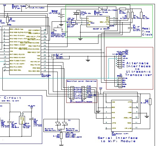
For your info, kenruizal, I agree with Dave on his statement above. The WizFi210 is expensive and difficult to program. I did a thorough evaluation on the available WiFi modules and ended up selecting the ConnectOne iWiFi MiniSocket Module. I recommend you use a ConnectOne iWiFi MiniSocket Module on a PCB interfaced to a PIC chip via a SparkFun level converter like I did (if you have to use 5V on the PIC for interface to your PIR sensor....if not you can run everything on 3v and eliminate the SparkFun level converter...see my schematic in above post). It is easy to program in PBP to command the MiniSocket module with its AT+i commands. It can be purchased for ~$58 for plugin to your PCB via a 2x6 female header. Then once you have debugged the code while running on your PCB you can further reduce the cost by using ConnectOne's reference design and do a 2nd generation PCB with all the iWiFi module components mounted directly on the PCB as surface mount devices.
I can help you with a couple of subroutines I developed that are tested and working with the MiniSocket. These subroutines connect to an external website via the internet and post data to it, as well as another one to send emails. You can also program it as a TCP listening socket and command it from the internet side. If you need help on this, start a new thread and point me to it via a Personal Message and I will help you get it working.
i tried to email connect one but no one reply us...can you give me a number or an email of connectone because i came from asia philippines...plz
Daniel Doron [[email protected]] from ConnectOne's Tech Support has been very responsive to me.
I wouldn't go that far. The WizFi210 itself is inexpensive, retailing for $30US but the Evaluation Board which the OP proposed using costs $110US so is rather expensive. For setting the configuration, the WizFi210 also uses an AT command set similar to what ConnectOne uses so, while it lacks a few protocols (email, network time), programming looks fairly simple. It has two ADC pins and several DIO pins as well as multiple communications methods (Serial, SPI, I2C, etc.). It's main drawback is the need for a custom designed PCB.
That it has ADC functions is intriguing. It really makes no sense to have them if you can only read them with a microcontroller since you could likely do that more easily with the microcontroller ADC channels. There is an app note (HTTP Data Transfer) that appears to show how to read a sensor over HTTP but, like most of their documentation, is sparse and difficult to understand.
sir what part number of your mini socket iwifi and model maker?tnx
john...what is best to be used it is with evaluation board or without evaluation board mini socket iwifi?
Hello john and mackrackit..if it is ok to you..can i have ur schematic in full...tnx
uhm..Sir what must be use in oscillator is it ok 4mhz or 8mhz?..what software do you use to load into pic18f4550 sir?...
 Members who have read this thread : 0
You do not have permission to view the list of names.
 Posting Permissions

Bookmarks