


Hi Guys,
This idea might sound silly, but I can't logically disqualify it, or practically check it at the moment,
but take any old LED matrix for POV display such as this:
So we get a number of LEDs which is the number of IO pin inputs multiplied by the number of IO pin outputs.
If we want more LEDs we go and get port multipliers.
The pic does the logic, but we introduce rows of transistors to source and sink the current as the display
gets larger (since the pic can sink more current than it can source, sometimes can get away with one row).
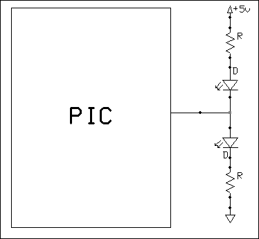
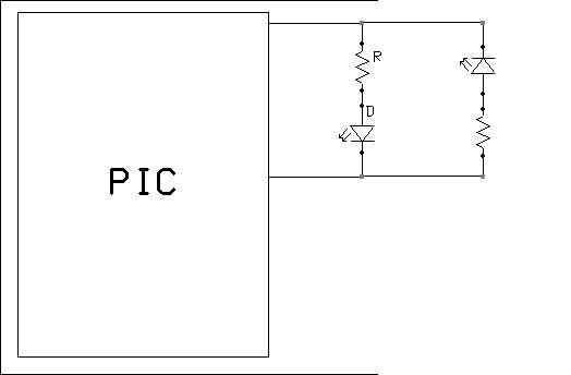
What if we got the above display working in a typical POV display circuit,
then duplicated the display circuit, but with reverse polarity, and configuration of transistor rows to match,
and then connected the second display circuit to the same pic IO pins that are driving the first display,
then just change the tris on every IO pin (inputs change to outputs and vice versa), to address the second display.
Could we double the LEDs for the same number of pic pins this way?


Bookmarks