2 Beam Optical Pulse Generator


Closed Thread
Results 1 to 9 of 9
  1. #1
    Join Date
    Jan 2010
    Location
    PHILADELPHIA, PA - USA
    Posts
    34

    Default 2 Beam Optical Pulse Generator

    Greetings,

    I developed this pulse generator to create an Optical High Resolution Timer and Speed Measuring device. It uses two laser beams as gates.


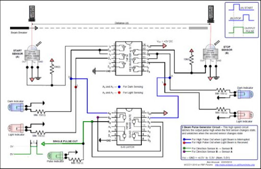
    2-BEAM OPTICAL PULSE GENERATOR
    (download high resolution PDF file below)

    I've been having a great deal of fun with it and thought I'd share it with you all.
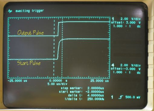
    I have no way of measuring the optical lag, however the circuit itself is quite fast and produces a clean output signal. Any optical lag should cancel, as the start and stop signals are treated the same way. Here's a scope shot that shows the response.


    It takes two individual OSRAM optical sensor outputs and produces a single pulse that rises on the rising edge of the start sensor, and falls on the rising edge of the stop sensor. The OSRAM sensors are very nice, they are sensitive to all optical wavelengths and have a built in Schmitt trigger.

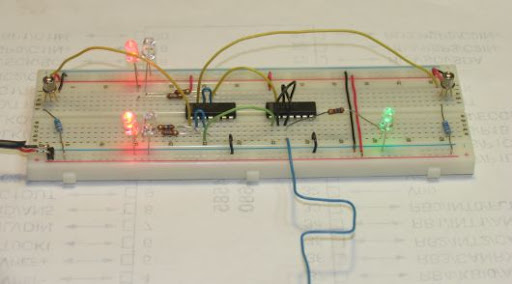
    This circuit which uses a Set-Reset Latch built from feeding back two NAND gates on the 74F00. This allows me to bring the signal into a single PIC pin. I then can use timer-1 to determine the pulse width. Here's an image of the prototype circuit:


    Anyway, I've learned so much from this forum that I thought It was time to reciprocate a little. Please feel free to comment on the circuit design, as I'm always learning.

    The rest of the project is going pretty well, and now I'm down to just a few tweaks to optimize the code to allow for error corrections and to maximize precision. (I'll post the full code and PIC portion of this project soon)

    Thanks to all the great educators, patient teachers and generally really smart folks on PBP Forums.

    Bob
    Attached Images Attached Images
    Wozzy-2010

  2. #2
    Join Date
    Jan 2010
    Location
    PHILADELPHIA, PA - USA
    Posts
    34


    Did you find this post helpful? Yes | No

    Default Circuit Notes

    Notes on 2-Beam Optical Pulse Generator Circuit.

    The cross wired 74F00 NAND Gate forms a Set-Reset Latch due to feedback from the opposing output.
    The output signal goes high when the first sensor is activated.
    The output remains high until the second sensor is activated.
    It is then reset, and ready for next cycle, no arm or reset button is necessary.
    The first sensor needs to be clear, before the second sensor is activated.
    Note that direction does matter, the circuit will not work if the sensors are activated in reverse order.

    This circuit can be quickly converted to a single sensor pulse generator, by fixing the Second sensor in active state, or shorting its output to ground. The Pulse Out will then follow the First Sensor only.

    OSRAM SFH-5840 is Active LOW, used in this circuit (Due to availability)
    OSRAM SFH-5841 is active HIGH, could simplify circuit by not requiring the inverters.
    The SFH-584X is sensitive to broad spectrum visible wavelengths, nearly any visible light source can be used.

    74F14 Hex Inverter includes Schmitt Trigger.
    74F04 Hex Inverter could be substituted because the SFH-5850 has a very clean output.

    If using remotely mounted sensors, remote mount the Indicator LEDs nearby to facilitate the optical alignment.
    (Probably really only need one LED per sensor)

    This circuit can be used as a latching pulse generator for nearly any TTL or 5V sensor or input in lieu of the SFH-584X.

    Average Speed = d/t
    The average speed through the two gates.
    d = distance between photo gates.
    t = time output pulse is high.


    --Bob
    Wozzy-2010

  3. #3
    Join Date
    Nov 2003
    Location
    Wellton, U.S.A.
    Posts
    5,924


    Did you find this post helpful? Yes | No

    Default

    Hi WOZZY,

    Thanks for sharing this. It give me some ideas...
    Dave
    Always wear safety glasses while programming.

  4. #4


    Did you find this post helpful? Yes | No

    Default

    Thanks for sharing. If this was some project where you had to use flip-flops or something then I get it. However, (and I know I'll take crap for this), I have to ask; couldn't all of the above been done with just one PIC (pick your type and flavor)?

  5. #5
    Join Date
    Jan 2010
    Location
    PHILADELPHIA, PA - USA
    Posts
    34


    Did you find this post helpful? Yes | No

    Default

    mtripoli,

    You're probably right.

    However the 74FXX chips cost less than $0.20 each.
    Their switching speed is phenomenal...on the order of 3nS
    My PIC timer project has a measurement resolution of 200nS.

    Do you think that the PIC could react this fast?

    This circuit kind of evolved from an earlier circuit that could control the Set and Reset function of a precision bench-top frequency counter / timer that I have. That controller needed 2 S-R latches. one of which I also use to control PIC timer for comparison

    I can use the bench-top unit to determine error corrections for the PIC timer

    The PIC timer uses CCP1 and TIMER1 instant interrupts to count clock pulses from a single pulse on a single pin.
    The core engine of the was put together by Bruce, Based on Darrel's instant interrupts.
    See: http://www.picbasic.co.uk/forum/show...01&postcount=3

    Thanks for the suggestion.
    Bob W.
    Wozzy-2010

  6. #6
    Join Date
    Nov 2003
    Location
    Wellton, U.S.A.
    Posts
    5,924


    Did you find this post helpful? Yes | No

    Default

    I like this for a couple of reasons.

    Most of the logic is done outside of the PIC. The latching of one till the other is triggered and re-setting when the second is triggered seems like some code load would be taken from the PIC.

    A one PIC pin solution. Often we find that more I/Os are needed, leading to multiple PICs or larger PICs just for a pin or two. Off the top I would probably use two PIC pins if I were doing this PIC only.

    Many ways to do anything. This project is a good reminder that a MCU is not always needed or can be complimented with external circuitry.

    Now if I could just remember how to make LEDs blink without a MCU
    Dave
    Always wear safety glasses while programming.

  7. #7
    Join Date
    Jan 2010
    Location
    PHILADELPHIA, PA - USA
    Posts
    34


    Did you find this post helpful? Yes | No

    Default Timer Code

    I posted the Code and PIC schematic part of this project in Code Examples Here:
    http://www.picbasic.co.uk/forum/showthread.php?t=12634

    -- Bob
    Last edited by WOZZY-2010; - 7th February 2010 at 06:13.
    Wozzy-2010

  8. #8
    marvelaugusts's Avatar
    marvelaugusts Guest


    Did you find this post helpful? Yes | No

    Default

    Is this true, An optical top hat pulse generator controlled by solitons. The top hat generator comprises a non-linear optical loop mirror (NOLM) that is fed by a continuous wave (CW) optical signal and is controlled by incoming optical pulses comprising first order solitons. The soliton regime for the incoming optical pulses is obtained by choosing a fiber with the correct dispersion and by adjusting the peak power of the control pulses.

  9. #9
    Join Date
    Jan 2010
    Location
    PHILADELPHIA, PA - USA
    Posts
    34


    Did you find this post helpful? Yes | No

    Default

    Nah... It's actually much simpler than that?!
    Wozzy-2010

Similar Threads

  1. Pulse Capture and byte building
    By boroko in forum mel PIC BASIC Pro
    Replies: 2
    Last Post: - 21st July 2009, 01:59
  2. Single digit 7 Seg LED clock - PIC16F88
    By thirsty in forum Code Examples
    Replies: 4
    Last Post: - 17th July 2009, 08:42
  3. Replies: 3
    Last Post: - 13th September 2008, 17:40
  4. Replies: 20
    Last Post: - 13th May 2007, 05:10
  5. Microcontroller with 2 way paging application problem
    By oneohthree in forum mel PIC BASIC Pro
    Replies: 30
    Last Post: - 20th April 2007, 17:27

Members who have read this thread : 1

You do not have permission to view the list of names.

Tags for this Thread

Posting Permissions

  • You may not post new threads
  • You may not post replies
  • You may not post attachments
  • You may not edit your posts