

Hi.After a little time,Servo resets 16f877a when I make power on .I know i need to use opto-isolator and i have 4n35 but i dont know what connections are required.Somebody can tell me?Thanks everybody who answers my question...


Hi.After a little time,Servo resets 16f877a when I make power on .I know i need to use opto-isolator and i have 4n35 but i dont know what connections are required.Somebody can tell me?Thanks everybody who answers my question...
Last edited by burak450; - 30th September 2008 at 01:49.
If you do not believe in MAGIC, Consider how currency has value simply by printing it, and is then traded for real assets.
.
Gold is the money of kings, silver is the money of gentlemen, barter is the money of peasants - but debt is the money of slaves
.
There simply is no "Happy Spam" If you do it you will disappear from this forum.
thanks for your response but I mean what connections are required between 16f877a and 4n35 and servo motor?

Connect the output pin of the pic to pin 1 of 4n35 via a resistor of 330 ohms connect pin 2 to digital ground. you can also place a led diode in series (between pic and opto to detect the state)
Pin 4 and 5 (4nn35) will be used to drive your servo (max current 150mA) if you need more current you must use a power transistor or a mosfet. Connect to analog ground pin 4 and pin 5 to your servo ground side. Connect the positive analog voltage directly to the servo.
When your pic pin will go high the opto will conduct switching on your servo.
I am sorry but i dont get exactly.Can you send any proteus file to here?
my servo is this http://www.rcuniverse.com/market/item.cfm?itemId=230128
what kind of circuit should I use?
Find enclose the schematic. You should separate the supply of the pic from the supply of the servo to avoid the electrical noise generated by the servo will disturb the functionality of your pic. Remember that 4N35 can supply a maximum current of 50 mA so if you want to use the schematic as it is, you must check that your servo does not need higher current. Naturally you do not need to change the software, because the wiring will give you a direct interfacing.
Hope this will solve your problem.
Forgive me i asked too many questions but i am a rookie about pic.my servo motor has three cable.+5 volt,ground and i have another cable as signal cable.Where do I connect signal cable??? Thank for your patience...
. . . . . If using the opto . . then to that . . . otherwise to the pic . . . . Why use the optoisolator . . .are you using some dangerous voltage, somewhere ? Or just trying to keep servo isolated from pic?Originally Posted by burak450

If you do not believe in MAGIC, Consider how currency has value simply by printing it, and is then traded for real assets.
.
Gold is the money of kings, silver is the money of gentlemen, barter is the money of peasants - but debt is the money of slaves
.
There simply is no "Happy Spam" If you do it you will disappear from this forum.
I am just trying to keep servo isolated from pic.my question is that where should I connect orange cable?

You really shouldn't NEED to isolate your servo from your PIC as long as you have a well designed circuit to drive it. I've used servos with my PICs, never had a need to isolate them, ran them off the same battery pack, same wires, etc.etc.etc.
If you're trying to run a PIC and a servo off a 9v battery (the little rectangular ones) connected to a single 7805 type regulator without any sort of cap's in the circuit anywhere, well, then, yes, you will most likely have a problem.
Maybe if we saw your schematic, we could help you figure out a way to avoid the isolator altogether...
Maybe you forgot to put a pullup on MCLR...maybe your oscillator setup is a bit goofy...maybe you got peanut butter in your chocolate...Who knows...

Hi, Burak
THIS could be a geat help :
http://www.parallax.com/Portals/0/Do...ic/Signals.pdf
Alain
************************************************** ***********************
Why insist on using 32 Bits when you're not even able to deal with the first 8 ones ??? ehhhhhh ...
************************************************** ***********************
IF there is the word "Problem" in your question ...
certainly the answer is " RTFM " or " RTFDataSheet " !!!
*****************************************
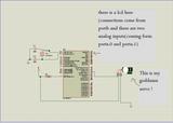
I am trying to design an object tracker (only left and right) and I am using phototransistors by using two analog inputs.I have to explain my problem more clear.When I turn power on servo tracks object but after a while sometimes pic resets itself or servo motor suddenly stops.I hope
I explained it clearly.What do you suggest? Here is my design.When you see the design there is a lcd.I use it for watching the values of analog input.When servo rotates,brightness of lcd changes (getting brighter or darker)...I think thats another weird thing...
Last edited by burak450; - 1st October 2008 at 02:17.
Doesn't that right there tell you something about the quality of your power supply?
Let's see...if I'm driving down the road, and my headlights change brightness, does that tell me anything about the electrical power in the car? If I'm sitting in my living room at night reading a book and the room's lights either dim or get brighter, would that tell me something about the local power grid?
I don't see ANY capacitors in there, either across Vdd and Vss or across your servo's power supply. I don't see what kind of power you are supplying this circuit with. I don't see a lot of anything.
Ya know, for that matter, we haven't seen your code yet... Who knows...maybe it is actually a firmware problem...
I would agree with Skimask re: the capacitors and your power supply, I would add, disable Brown Out Reset in your config statement so PIC does not reset, I would further suggest you change your reference to God Blessed servo, just remembering something Moses said to Pharoe, "by your own words . . ." Cause if he Damns it, it's toast.
If you do not believe in MAGIC, Consider how currency has value simply by printing it, and is then traded for real assets.
.
Gold is the money of kings, silver is the money of gentlemen, barter is the money of peasants - but debt is the money of slaves
.
There simply is no "Happy Spam" If you do it you will disappear from this forum.
Hi, Burak from your schematic and your explanation I understand that is just a power supply problem! Add 10nF capacitor to the Vdd pic pin. Since surely you are using battery, my suggestion is that you use a two 9 volts batteries in parallel to a 7805 and use its output as power supply for your project. One way to check quickly that current failure is your problem, can be achieved simply removing (disconnect it) the backligth of your lcd, and very likely the problem will disappear as long as the present battery will be able to supply the required energy
i should repeat that=Lcd brightness doesnt change at normal work. when servo moves than it goes high or low...
my power supply is that.
switching adapter
input:ac 100-240V-50hz 0.36A
output:dc 5v--2.5A
and my program is that
Code:DEFINE LCD_DREG PORTB DEFINE LCD_DBIT 0 DEFINE LCD_RSREG PORTB DEFINE LCD_RSBIT 4 DEFINE LCD_EREG PORTB DEFINE LCD_EBIT 5 DEFINE LCD_BITS 4 DEFINE LCD_LINES 2 DEFINE OSC 4 DEFINE ADC_BITS 8 DEFINE ADC_CLOCK 3 DEFINE ADC_SAMPLEUS 100 SYMBOL F=PORTA.0 SYMBOL G=PORTA.1 alta var byte usta var byte altb var byte ustb var byte ADCON1=2 TRISA=3 TRISB=0 PORTB=0 TRISC=0 LCDOUT $FE,1 pause 4000 adcin 0,ALTa ADCin 1,usta t var byte i var byte T=150 yap: adcin 0,altb ADCin 1,ustb if ((((usta+10)*100)/(ustb+10)))>135 then T=T+15 endif if (((alta*100)/altb))>135 then T=T-15 endif gosub motor LCDOUT $fe,2,#usta," ",#ustb," ",#altA," ",#altb goto yap motor: for i=0 to 25 PULSOUT PORTC.2,T PAUSEUS 20000-(T*10) next return end
Last edited by burak450; - 1st October 2008 at 11:37.
Check power supply wiring, especially the connector, install 1000 uF 16V electrolytic capacitor and 10 nF on your pic power pin
For grins, try changing your BYTE values to WORDs and see what happens.
Might be overflowing the byte values somewhere killing the program somehow someway.
Hi, Burak
I'm curious to know which testboard you use ...
16F877A , LCD on PortB ... that sounds quite familiar.
So, the question is ... Where do you ( geographically ) take the servo 5v supply from ???
Alain
Last edited by Acetronics2; - 1st October 2008 at 15:46.
************************************************** ***********************
Why insist on using 32 Bits when you're not even able to deal with the first 8 ones ??? ehhhhhh ...
************************************************** ***********************
IF there is the word "Problem" in your question ...
certainly the answer is " RTFM " or " RTFDataSheet " !!!
*****************************************
Use a separate power supply for your servo.
Bruce thanks for advice,i tried million times but couldnt connect separate supply correctly.I think you mean opto-isolotor circuit.Do you suggest any opto-isolator circuit??
Some guys said i dont need this circuit.I am confused now.
Acetronics,I took 5v supply to servo from same source where I took power to pic.I mean servo and pic is feed same source...

Hi,
16F877a has got a Power Control Register (PCON). Section 14.10 page 151 in the datasheet.
In the top of your code just after you initialize the LCD. Read the PCON into some variable and display it on the LCD for say 5 seconds. Note it down just after a reset. This may help decide the cause of the reset---> Brown Out, WDT, MCLR etc.
Also make sure that your RB3 (Pin 37) is not floating. It is the LVP pin and noise on that can trigger the ICSP mode.
Just for information on the opto part you can use a TLP250 optocoupler (works upto a few khz) which has got a totem-pole output. So you drive the LED and get a 0-1 on the output. I use it mainly for my IGBT driver needs.
Last edited by sougata; - 1st October 2008 at 16:08. Reason: Mentioned the opto
Regards
Sougata
You should not need an opto, but you may want to include the series resistor shown in the .PDF Alain linked to.
A separate power supply for the servo is a good idea, but you need a common ground connection between the two power supplies.
Most hobby type servos will work fine with a DC supply of ~4.8 to 6Vdc. I normally use a set of 4 x D cells. Just connect the ground leg from your batteries to the ground leg of your regulated supply for the controller.
If you use another regulated supply for the servo, make sure it can handle the servo load current. A servo can draw quite a load. Some up to 1A or more. Having this load on your primary supply can drop voltage and cause a device reset. With separate supplies you shouldn't have this problem.
Ok, Folks
I've got it ...
Servo driving values on C.2 go out of the nominal 0.8 - 2.2 ms range OR Pause between pulses goes wrong.
Servo bumps on its mechanical stops ... or the amp doesnt like the pause !!!
That's all !
Alain
Last edited by Acetronics2; - 1st October 2008 at 16:10.
************************************************** ***********************
Why insist on using 32 Bits when you're not even able to deal with the first 8 ones ??? ehhhhhh ...
************************************************** ***********************
IF there is the word "Problem" in your question ...
certainly the answer is " RTFM " or " RTFDataSheet " !!!
*****************************************
Acetronics,
Can you explain it more clear,i dont get what you mean.Is there any solution on your mind?
Hi, Burak
The only solution is for you to verify you send correct signals to your servo ...
800 to 2200 µs @ 35 - 50 Hz ... only allowed.
Nothing more or less to say !
Alain
************************************************** ***********************
Why insist on using 32 Bits when you're not even able to deal with the first 8 ones ??? ehhhhhh ...
************************************************** ***********************
IF there is the word "Problem" in your question ...
certainly the answer is " RTFM " or " RTFDataSheet " !!!
*****************************************
Hi Acetronics,
I think you are wrong because my signal is 50hz.I am using 20ms periodic pulses,if t=100 then 1ms high and 19ms low.if the period 20ms then frequency will be 50hz from the formula f=(1/T)
here is my signal code
PULSOUT PORTC.2,T
PAUSEUS 20000-(T*10)
where am I wrong?
Look at the loop in your code.
Aboslutely no 'bounds' checking.
What if...T = 0? Then pauseus = 20000, ok no problem...
What if T=2000? Then pauseus = 0, ok not much of a problem...
What if T=2001? Then pauseus = 65526, ok, shouldn't happen because you've got T defined as a BYTE
But...what happens when you try to drive the servo out of it's physical limits?
What happens to the current draw if you hold a servo that's trying to move? Hook up an ammeter and find out real quick. And if you don't have an ammeter, hook up a voltmeter to your 'battery' and try it and see what happens to your voltage...
Lol ...
It has been verifyed with a R/C Pulsemeter.
Checks pulse AND repeating frequency ...
Y've done the mods to have your program running ...
Runs awfully bad for a tracker, but runs ... on the USB supply from my PC. ( 500 mA ! )
YOU are wrong in your calculations ... that's it !!!
************************************************** ***********************
Why insist on using 32 Bits when you're not even able to deal with the first 8 ones ??? ehhhhhh ...
************************************************** ***********************
IF there is the word "Problem" in your question ...
certainly the answer is " RTFM " or " RTFDataSheet " !!!
*****************************************
Hi Acetronics,
First of all,calm down
I just said my idea...
I havent got R/C Pulsemeter,I cant measure the pulses...
Probably your calculations are right.I am here because my project doesnt work correctly and want to have second opinion.
Can you give me the right code ?
will only changing variable type byte to word be enough????
Probably not...will only changing variable type byte to word be enough????
Think about this...
How long does it take for ADCIN to execute?
How long does it take for LCDOUT to execute?
And fix your power supply...
And fix your power supply...
as you said that you mean same ground but another power supply...
did I understand right?
No I mean read back thru the thread! I don't see any mention of adding any capacitors anywhere in the circuit...except where somebody but you has mentioned them...
And, you say you are using a switching adapter, like a wall-wart rated at [email protected]?
How long is the cord feeding the PIC/servos? How much 'noise' is getting to your PIC? How much 'noise' does your servo generate under a load? Any capacitors in there anywhere?
http://en.wikipedia.org/wiki/Decoupling_capacitor
Hi, Burak
Don't worry for me ... I always am calm.
I Exceptionnaly cook code for others ...
so,
- you'll fist check "T" calculations and do not allow it to go out of the 800 - 2200 µs range
- Check for a "decent" increment to the same "T" variable
- Understand that 50 Hz is not a MUST ... just be in the 35-50 Hz range; doesn't need to be a constant frequ. nor.
PS: "Give me THE code" or "Give me THE scheme" are the sentences that suddently re activate my Altzheimer ...
What Were we talking about ??? ...
Alain
************************************************** ***********************
Why insist on using 32 Bits when you're not even able to deal with the first 8 ones ??? ehhhhhh ...
************************************************** ***********************
IF there is the word "Problem" in your question ...
certainly the answer is " RTFM " or " RTFDataSheet " !!!
*****************************************
Ok.I wont want you to give code because i know Altzheimer is very tough disease
I am gonna try what you said.If I fail I will disturb you again
Thanks for help up to now....
Why not just write simple code to sweep servo left to right and back right to left for testing? BTW, if you use a 5v regulator with 5v output power supply, it will cause a power drop when you try to draw current. A voltage reg will probably need 6.5v++ input voltage. Also, I have driven 4 large servos off of 2 paralleled voltage regs and a low current reg for the pic....no problems at all.
Hi, Burak
We haven't solved the power problem ...
so, I ask the question once more : Which is your testboard ???
Alain
************************************************** ***********************
Why insist on using 32 Bits when you're not even able to deal with the first 8 ones ??? ehhhhhh ...
************************************************** ***********************
IF there is the word "Problem" in your question ...
certainly the answer is " RTFM " or " RTFDataSheet " !!!
*****************************************
Macgman2000 wants my code...
I wrote a new code to protect values which makes out of range.
Code:DEFINE LCD_DREG PORTB DEFINE LCD_DBIT 0 DEFINE LCD_RSREG PORTB DEFINE LCD_RSBIT 4 DEFINE LCD_EREG PORTB DEFINE LCD_EBIT 5 DEFINE LCD_BITS 4 DEFINE LCD_LINES 2 DEFINE OSC 4 DEFINE ADC_BITS 8 DEFINE ADC_CLOCK 3 DEFINE ADC_SAMPLEUS 100 SYMBOL F=PORTA.0 SYMBOL G=PORTA.1 alta var byte usta var byte altb var byte ustb var byte ADCON1=2 TRISA=3 TRISB=0 PORTB=0 TRISC=0 LCDOUT $FE,1 pause 4000 adcin 0,ALTa ADCin 1,usta t var byte i var byte T=150 yap: adcin 0,altb ADCin 1,ustb if ((((usta+10)*100)/(ustb+10)))>130 and (not (t>194)) then T=T+15 endif if (((alta*100)/altb))>130 AND (not (t<51)) then T=T-15 endif gosub motor LCDOUT $fe,2,#usta," ",#ustb," ",#altA," ",#altb lcdOUT $fe,$C0,#T goto yap motor: for i=0 to 25 PULSOUT PORTC.2,T PAUSEUS 20000-(T*10) next return end
I am using breadboards.A minute ago i tried to connect two parallel power supply.Servo didnt reset MCU.I was glad but sometimes when i turned power on ,servo turned full left sometimes didnt.I think my servos are crazy.BTW I connected a capacitor.
I have an idea.Can this error(full left error) occur because of my code that i wrote.too many PAUSEUS may make this error.Should I try DUTYCYLE or PWM codes???
Or Is there any power problem???
If you have an oscilloscope look at your control pulses from the PIC to the servo as it moves. If you see that the wave form (1~2ms pulse) is wiggling around or changing amplitude then you have a power supply issue. Do as I suggested above, get a 9v power supply (AC/DC) and use TWO 7805 regulators in parallel for the servo ONLY. At the servo use 470uF across power and ground. Look at the scope again and make sure you see a "cleaned" up signal while servo is in motion.
Nick
In the middle of that math mess? I don't think it's a good spot for it...but that's just me...I wrote a new code to protect values which makes out of range.
Code:DEFINE LCD_DREG PORTB DEFINE LCD_DBIT 0 DEFINE LCD_RSREG PORTB DEFINE LCD_RSBIT 4 DEFINE LCD_EREG PORTB DEFINE LCD_EBIT 5 DEFINE LCD_BITS 4 DEFINE LCD_LINES 2 DEFINE OSC 4 DEFINE ADC_BITS 8 DEFINE ADC_CLOCK 3 DEFINE ADC_SAMPLEUS 100 f var porta.0 : g var porta.1 : alta var byte : usta var byte : altb var byte ustb var byte : t var byte : i var byt e: adcon1=2 : trisa=3 : trisb=0 portb=0 : trisc=0 : pause 1000 : lcdout $fe,1 : pause 4000 adcin 0,ALTa : ADCin 1,usta : t=150 pulsout portc.2,t 'initial servo kick to center yap: adcin 0,altb : adcin 1,ustb if ((((usta+10)*100)/(ustb+10)))>130 and (not (t>194)) then T=T+15 if (((alta*100)/altb))>130 AND (not (t<51)) then T=T-15 'bounds checking... if t < 100 then t=100 if t > 200 then t=200 'bounds checking 'if 100 isn't low enough, change it, if 200 isn't high enough, change it gosub motor : lcdout $fe,2,#usta," ",#ustb," ",#altA," ",#altb, $fe,$C0,#T goto yap motor: for i=0 to 25 : PULSOUT PORTC.2,T : PAUSEUS 20000-(T*10) : next i return end
 Members who have read this thread : 0
You do not have permission to view the list of names.
 Posting Permissions


Bookmarks