Hi friends,
I know that this is a really old topic, but, last week I got 3 of this display for free from a friend.
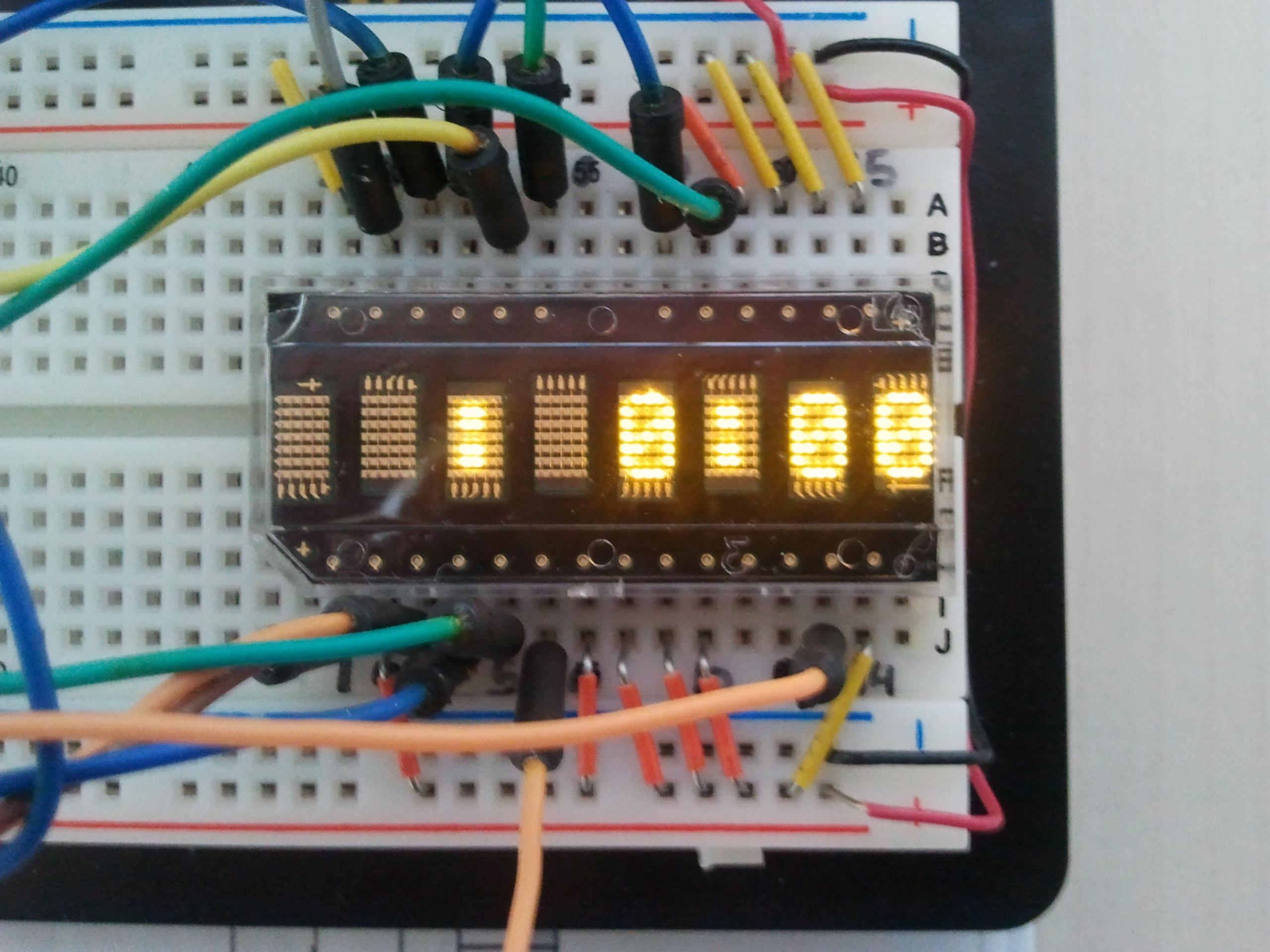
They are nice, bright, and has a good "retro" looking.
I did many many tests and I was unable to get a stable result from the display. They are brand new, never used.
I test the Rentron´s Hello moving message an the clock published here.
Both, I get ramndom characters and a strange behavior.
I´m using a 16F877 @ 10 Mhz (I did tests @ 20 Mhz also)
I´m using the wiring suggested by rentron :
'* // Display connections * //'
' PortB Display | PortA Display | PortC Display
' B0 #19 | A0 #3 | C0 #13
' B1 #20 | A1 #4 | C1 #6
' B2 #23 | A2 #5 | C2 #1
' B3 #24
' B4 #25
' B5 #26
' B6 #27
' * // Display GND, VCC and N.C. [no connection] * //'
' GND 15,16,17,28
' VCC 2,7,8,9,10,11,14,18
' N.C. 12
and the source code :
Code:
DEFINE OSC 10         ' 4MHz oscillator
@ ERRORLEVEL -306   ; Retira o erro de crossing page boundary
;@  __CONFIG  _CP_OFF  & _DEBUG_OFF & _CP_OFF & _CPD_OFF & _LVP_OFF & _BODEN_OFF & _PWRTE_ON & _WDT_OFF & _HS_OSC
@  __CONFIG  _HS_OSC &  _CP_OFF & _DEBUG_OFF  & _CPD_OFF & _LVP_OFF & _PWRTE_ON  & _WDT_OFF

TRISA   = 0         ' Setup PortA = output for Address Bus
TRISB   = 0         ' Setup PortB = output for Data Bus
TRISC   = 0       ' RC.7 = input, rest outputs [used for loader]
ADCON1  = 7         ' A/D OFF

A_Bus   VAR PORTA
D_Bus   VAR PORTB   ' PortB = Data Bus
W_Pin   VAR PortC.0 ' HDSP-2112 write strobe pin #13
A3      VAR PortC.1 ' HDSP-2112 mode select pin #6
FL      VAR PortC.4 'Flash mode select
RST     VAR PortC.2 ' HDSP-2112 reset pin #1
Digit   VAR BYTE[8] ' 8-byte digit array
DigPat  VAR BYTE    ' Digit pattern from lookup table
LP_Cnt  VAR BYTE    ' Loop counter
LowDig  VAR BYTE    ' Holds "low" digit # to lookup
LowDig  = 0         ' 1st digit = 0
HiDig   VAR BYTE    ' Holds "high" digit # to lookup
HiDig   = 7         ' Last digit = 7
J       VAR BYTE    ' Array index pointer
J       = 0         ' 1st byte in array
S_Speed VAR WORD    ' Holds display scroll speed
S_Speed = 200      ' Set display scroll speed here
Low D_Bus.7         ' Set display for normal operation
EOM     CON "~"     ' Character used as "End of Message" marker
hour    VAR     BYTE    ' Define hour variable
dhour   VAR     word    ' Define display hour variable
minute  VAR     BYTE    ' Define minute variable
second  VAR     BYTE    ' Define second variable
ticks   VAR     BYTE    ' Define pieces of seconds variable
update  VAR     BYTE    ' Define variable to indicate update of LCD

second10 var byte
min10   VAR BYTE
hour10  VAR BYTE

i var word
ADCON1 = 7
        second10 = 0
        hour = 0       ' Set initial time to 01:00:00
        hour10 = 6
        minute =  0
        min10  = 0
        second = 0
        ticks = $00


        update = 0

        OPTION_REG = $55        ' Set TMR0 configuration and enable PORTB pullups
        INTCON = $a0            ' Enable TMR0 interrupts
        On Interrupt GoTo tickint
                 '
'* // Initialize display - then set brightness * //'
Init_Display:
    ' * // Initialize Display Here * //'
    High W_Pin : Low RST : Pause 20 : High RST : High FL : Pause 20

    ' * // Set Display Brightness Here * //'
    ' To change display brightness
    ' D_Bus = |  0   |  1  |  2  |  3  |  4  |  5  |  6  |
    ' Bright =| 100% | 80% | 53% | 40% | 27% | 20% | 13% |
    '
    ' Set 27% | mode.bit | strobe settings into display |
    D_Bus = %0001100 : Low A3 : Low W_Pin : High W_Pin
    High A3 ':HIGH FL' A3 used only for setting display brightness


'* // Get 8 digits into "Digit Array" for display * //'
GetDig:


    For LP_Cnt = LowDig TO HiDig
       LookUp LP_Cnt,["  :  :  "],DigPat
        Digit[J] = DigPat   ' Load all 8 digits into array
        J = J + 1           ' Increment array index pointer
    Next                    ' Loop until we have all 8 digits loaded
    J=0                     ' Re-set array index pointer
    LowDig = LowDig      ' Increment to next "low" digit
    HiDig = HiDig       ' Increment to next "high" digit


'* // Display 8 digits on display then return for more // *'
DisplayDigit:
   For LP_Cnt = LowDig TO HiDig     ' Scroll right-to-left


     A_Bus  = LP_Cnt        ' Place digit address on address bus

      D_Bus = Digit[J]      ' Place digit data on data bus
      Low W_Pin : High W_Pin' Strobe data into display
     J = J + 1            ' Increment array pointer to next digit
     DigPat = DigPat

    Next
    J = 0

   chkup:
                'While hour = 1 and hour10 = 3
                '       hour = 0
                '       hour10 = 1
                '       wend

               A_Bus  = 7
                 D_Bus = 48 + second10
                 Low W_Pin : High W_Pin
                   Pause 10

               A_Bus  = 6
                 D_Bus = 48 + second
                 Low W_Pin : High W_Pin
                   Pause 10

                A_Bus  = 4
                 D_Bus = 48 + min10
                 Low W_Pin : High W_Pin
                   Pause 10

                   A_Bus  = 3
                 D_Bus = 48 + minute
                 Low W_Pin : High W_Pin
                   Pause 10

                   A_Bus  = 1
                 D_Bus = 48 + hour10
                 Low W_Pin : High W_Pin
                   Pause 10

                   A_Bus  = 0
                 D_Bus = 48 + hour
                 Low W_Pin : High W_Pin
                   Pause 10

                  IF update = 1 Then

                 update = 0
                  endif
     Goto chkup

           Disable
tickint:
        ticks = ticks + 1      ' Count pieces of seconds

        IF ticks < 165 Then tiexit


' One second elasped - update time

        ticks = 0
        second10 = second10 + 1
        IF second10 >= 10 Then
          second10 = 0
          second = second + 1

        IF second >= 6 Then
                second = 0
                min10 = min10 +1
                IF min10 > 9 THEN
                min10 = 0
                minute = minute + 1
                IF minute >= 6 Then
                        minute = 0
                        hour10 = hour10 + 1
                        IF hour10 > 9  THEN
                        hour10 = 0
                        hour = hour + 1
                        IF hour > 2 Then
                                hour = 0


                                  ENDIF
                           ENDIF

                        EndIF
                EndIF
        EndIF

         ENDIF
        update = 1      ' Set to update LCD

tiexit:
         INTCON.2 = 0    ' Reset timer interrupt flag

        Resume
        End
Have someone here ever used this kind of display ?
thanks !
Sérgio


Bookmarks