


Dear Forum:
I'd like to build a small Clock with GPS time-sync, look, I'm using the Darrel instant interrups to drive the Timer 1 clock, it works great ! (Thanks Darrel !), but when I tried to read the GPS data (over Pin RB1) there is a lot of missed/corrupted bytes in my buffer, something like this:
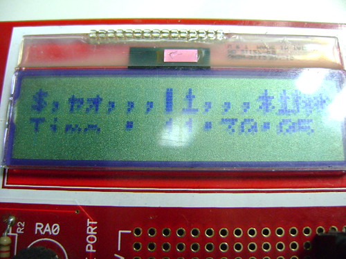
the first lcd line is the RMC message data (corrupted in this case) and the second line display the RTC registers, (plese note tha my LCD was broken so the lower line is wrong )
this is the code
my first idea to fix it,was stop the timer just before get the gps data stream, like this:Code:'''''''''''''' INCLUDES '''''''''''''''''''''''''''''''''''' DEFINE OSC 4 INCLUDE "DT_INTS-18.bas" INCLUDE "ReEnterPBP-18.bas" INCLUDE "Elapsed_INT-18.bas" INCLUDE "LCDPICDEM2.BAS" ' it runs on PIDEM2 PLUS Board ''''''''''''' VARIABLES '''''''''''''''''''''''''''''''''''' j var byte rmc var byte[100] ' this gets RMC data led1 var portb.2 b0 var byte adcon1 =$07 trisa.2 = 0 trisa.4 = 1 trisb.1 = 1 trisb.2 = 0 trisb.0 = 1 trisc.2 = 0 porta.2 = 0 gps var portb.1 spk var portc.2 ''''''''''''' CODE '''''''''''''''''''''''''''''''''''' init: ASM INT_LIST macro ; IntSource, Label, Type, ResetFlag? INT_Handler TMR1_INT, _ClockCount, PBP, yes endm INT_CREATE ENDASM T0CON = %10011010 @ INT_ENABLE TMR1_INT GOSUB ResetTime GOSUB StartTimer hours = 11 : minutes = 30: seconds = 0 Start: LCDOUT $FE,1 ' Initialize LCD PAUSE 200 lcdout $fe,2,"Starting ..." : pause 500 Main: serin2 gps,188,1000,no_gps,[wait("MC"),str rmc\15\10] '15 bytes only for testing () wait for RMC message lcdout $fe,$c0,"Time : ",dec2 hours,":",dec2 minutes,":",dec2 seconds lcdout $fe,2,"$",str rmc\15 :pause 500 ' these are the bytes as captured ! goto main no_gps: lcdout $fe,2,"Np Gps stream ": pause 500 goto main '''''''''''''''''''''''''''''''''''''''''''''''''''''''''''''''''''''''''''
using above lines my LCD looks like this:Code:gosub stoptimer serin2 gps,188,1000,no_gps,[wait("MC"),str rmc\15\10] '15 bytes only for testing () wait for RMC message gosub starttimer
looks good !!!
but here, I have a problem with the time !, this make delay on the RTC, If I just was updated my clock register each ten minutes or so, that work out very well, but I want to keep my RTC all the time, (for logging timed-stamp GPS locations by example).
I knew this is a time issue (software generated timing "serin2"), another plan is to use the internal UART build in my pic (i'm using a18f452), but my GPS only outputs TTL levels this create interfacing problems, how can I get working this project?
Thanks !!!


Bookmarks