


Hello Everyone,
I'm a new member to this forum.
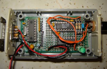
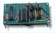
I am currently in the process of building a control board for an 8 servo biped walker using the PICPROTO 18 Prototyping Board.
Does anyone have any pictures or diagrams of their trace work and parts placement for any of the PICPROTO 18 board(s) they made ? Doesn't matter what the board was designed to do. (Note: The parts placement/tracework/schematic, etc. for the IC, regulator, caps, crystal etc. is already given w/ the sheet that comes with the board, so I'm not looking for that) or know where I can find some examples ?
I was hoping to lay down (solder) bar wire for the "traces" rather than run, jumper a bunch of insulated wire (spagetti) all over the place.
Thanks !,
Rick


Bookmarks