

thanks all
Originally Posted by Darrel Taylor


thanks all

Mike,
Did you get anywhere with this ...
I can not figure out a way to Charlieplex MIBAM.
I need to finish this thing, and think I'm going to have to toss Charlie out the window (from a very tall building).
DT
DT
What "thing" are you talking about tossing Darrel?
I wrote and simulated the ISR driver for a 5-pin 20-LED demo' but that's as far as I got. You want to see that part Sir?
<added>
Tell me what chip you want it for and I'll give you a simple 5-pin (rb0..rb4) 20-LED sample Saturday that you can breadboard and play with.
Mike
Last edited by Mike, K8LH; - 13th November 2009 at 00:48.
At this point, I'd like to toss Charlie Allen himself.
Is that with MIBAM? I'd love too.I wrote and simulated the ISR driver for a 5-pin 20-LED demo' ...
For whatever chip, in whatever language.
Even if it's not MIBAM, it might give me an idea that could save Charlie's life.
Thanks again Master,
DT
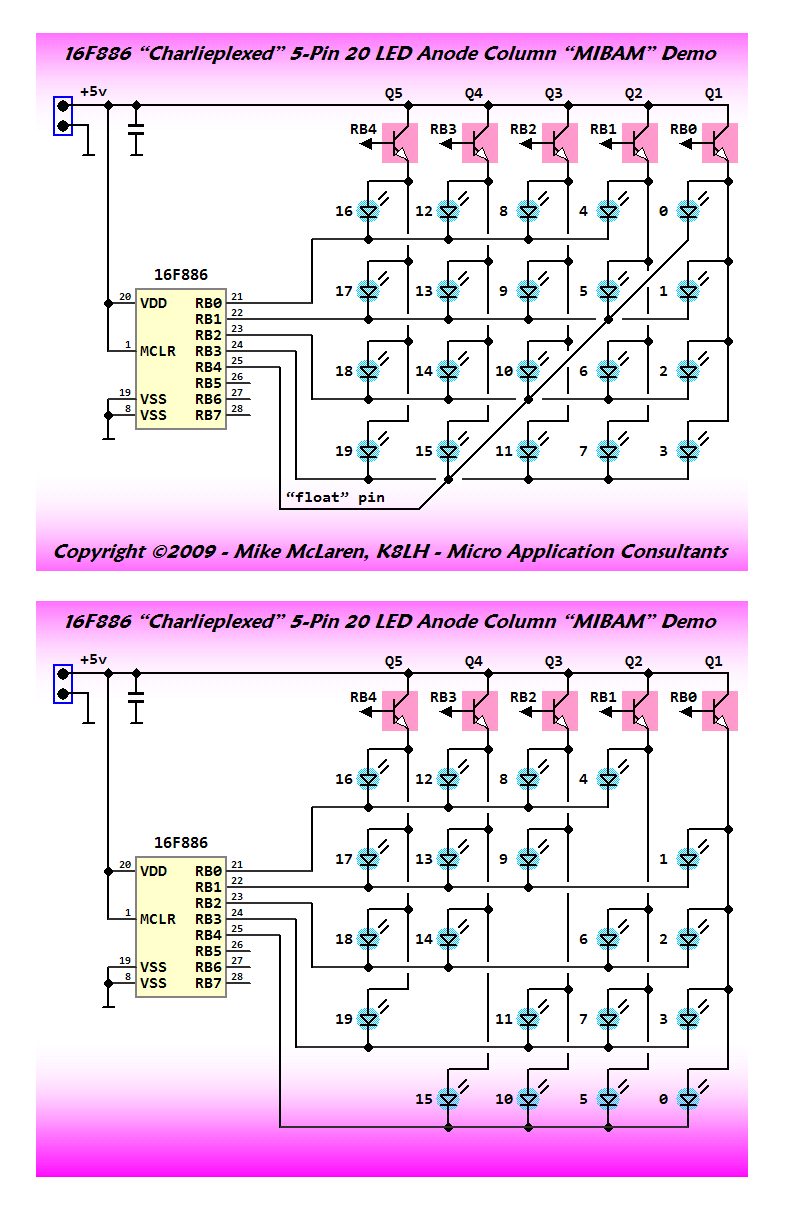
Yes, it's a sample ISR engine for MIBAM within an assembly language 'skeleton' program for 16F886 with 20 Charlieplexed LEDs on 5 pins (RB0..RB4). Just needs config lines, an init section, and short main section to manipulate the led[] array. I was interested in seeing if MIBAM could be implemented on a Charlieplexed matrix and after I wrote and simulated the MIBAM ISR 'engine' I got distracted by other projects.
I will send you the Charlie-MIBAM skeleton in a PM and work on those missing pieces so that you can actually try something on some hardware, if you like.
Mike
Last edited by Mike, K8LH; - 13th November 2009 at 22:59.
Someone asked about the diagonal line on my Charlieplexed display sketch. It's what I refer to as the "float" pin and it's connected to the LEDs that occupy positions in the matrix that would otherwise share a common column and row (RB0/RB0, RB1/RB1, etc.).
I apologize if the diagonal line has thrown you off. It's a remnant from some of my sketches of Charlieplexed 7-segment displays.
Both drawings below are electrically the same but the second drawing below may make more sense. Basically I just slid those LEDs in the bottom row up into the empty spaces in the matrix.
Kind regards, Mike
Darrel,
I was just wondering -- is MIBAM even necessary on a multiplexed display due to the long pauses between LED activation. You know, column one LEDs would be BAM'ed then turned off while we sequencially BAM column two LEDs, then BAM column three LEDs, etc.?
Hi Mike,
I wholeheartedly agree.
MIBAM with multiplexed display doesn't seem like it's worth it, because you loose so much of the available dutycycle.
Thanks for the explanation of the diagonal line.
I did get your example working, with only 8 leds (2 columns).
I made enough changes to not know if it's actually the way yours works or not.
But I don't see a way to incorporate it into the MIBAM routines (because of the duty cycle losses), so I'm officially tossing Charlie out the window.
Good thing I live at ground level.
I'll complete the modifications for your previous idea (full port updates) and get this thing done.
Thanks for all your assistance Mike, much appreciated.
DT
Yes, LED duty cycle is decreased with any multiplexed display and while we normally pump up the "peak" current to get better "average" current (and brightness) we can't do that with a Charlieplexed display (or any other multiplexed display that uses "direct drive" for matrix columns or rows).
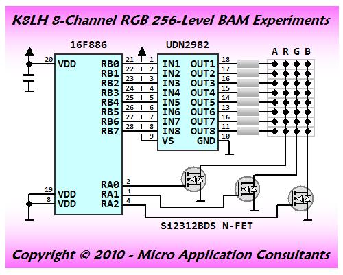
Anyway, I thought you might enjoy taking a peek at a multiplexed 8-channel RGB display demo' (24 discrete LEDs) with 256-level BAM driver and a pretty amazing 868-Hz refresh rate. The display is fashioned as a 3x8 matrix (33% duty cycle) so biasing the LED "peak" current to approximately 3x desired "average" current will be necessary. This assembly language program just contains the driver. No animation or anything like that, yet.
Regards, Mike
Last edited by Mike, K8LH; - 18th February 2010 at 23:06.
Is there any way I can get temporary access to locked post above to update the program listing? I posted incorrect version which has some bugs. Sorry!
Darrel (and gang),
A long overdue assembly language Charlieplexed BAM example for 20 LEDs on a 12F683. Example uses 8-bit 256 step BAM driver with a 1-usec step size. Refresh rate is 781-Hz with a 1280-usec frame rate. LED "0" is animated. That is, it ramps from duty cycle value of 0 up to 127 and then back down to 0. LED "10" through LED "19" are lighted with duty cycle values of 1 through 10 so you can check out "low end" illumination.
You might just hook up a single LED for LED "0" to check out the program. Just connect the LED cathode to GP5 and the LED anode to GP0.
Kind regards, Mike
Last edited by Mike, K8LH; - 5th March 2010 at 18:29.
Has anyone tried "gamma" correction to smooth out LED brightness level changes? I just added a 64 level rom "gamma" array to the program in the previous post and it made an amazing difference in the smoothness of the fade.

I supose this depends on the type of LED. Each type of LED may need its own gamma curve.
Ioannis
Bummer! I was afraid of that...
Hi Mike,
Fantastic work!
Could you please post:
LED Part number,
Gamma correction routine?
Please, Please, Pretty Please?
I've learned a lot from this thread and want to say Thank You, to ALL who have contributed.
73,
Terry K9HA
Hi Terry, K9HA,
Attached is assembler source with "gamma" table. I also slowed down LED "0" fade loop time considerably to look for "stair stepping" effect since I was only using 64 "gamma" steps but the fading is remarkably smooth.
I'm using Fairchild MV57164 Bar/Dot displays but almost any LED should work fine.
A couple observations;
(1) I'm very surprised at the light produced from LED "10" which is set to a duty cycle of 1 (1-usec -> 1/1280th or 0.078125% duty cycle).
(2) Mirrored BAM doesn't seem to be necessary to correct the 127-128 duty cycle transition visual artifact when using a multiplexed display (with gaps between LED updates).
Regards and "very 73", Mike, K8LH
Last edited by Mike, K8LH; - 9th March 2010 at 16:02.
Mike,
Thank you for the part data AND the assembly code.
It will be fun experimenting with this!
73
Terry
K9HA
I'm geeked!
Just added a 256-step BAM driver to an old project which had a 4-digit 7-segment display (direct I/O drive) and using it for brightness control works great (488-Hz refresh rate @ 4-MHz INTOSC).
I've got a few of these old three or four digit 'pnp' (practically no parts) type projects around and I had always wanted to implement a form of PWM brightness control on them but nothing worked as well or was as 'clean' as this K8LH BAM driver method.
Only "down side" so far is that I haven't figured out a way to implement "cycle accurate" delays in BoostC which means I'm stuck writing in assembler which no one can understand (lol).
Regards, Mike, K8LH
Last edited by Mike, K8LH; - 10th March 2010 at 16:45.
yep... tryed it in 3 ways:
1. Simple ISR-based software PWM with floating (table-generated) pulse widths.
2. Strobing /OE of external latches (54 PWM channels/PIC16f877a) with HW PWM output (table-generated) + SW PWM (i had to slightly increase LED current to get more brightness, as the full duty cycle hadn't been achievable, almost like with 1.5x charlieplexing)
3. Increased bit depth to 13(14) bit and PWM speed (refresh rate) to 610Hz on 18F for better perfomance.
2 ALL...
There is one small problem with high speed BAM/MIBAM. Problem exists if u use simpler MOSFET driving scheme (or if u use slower bipolar schemes like darlinghton's transistor pairs and if actual switches are controlled by MCU's outputs directly) or if u need higher current per channel, especially if currents on some channels are significantly different. This happens because switching delays differ too. Check out datasheets for gate driving characteristics for higher current applications and compare it with needed signal discretization. PWM methods don't solve the problem but it need less signal transitions per cycle and work slightly better for lower bit depths without additional gate drivers (for reasonable currents, of course). Actually this problem just increase duty_cycle/brightness relation's non-linearity, but combined with longer wires, bad PCB layouts etc. it may cause unpredictable results for visual perception. So don't be surprised). sorry, can't describe problem in detail because of my poor english (lack of practics) and lazyness. Anyway, best solution is to check your application's requirements in advance))).
Last edited by sanch0; - 1st April 2010 at 01:03.
hi,sanch0.
how r u?
i am waiting for ur codes for 16 channels of 14-bit BAM, at 610Hz.
where are them?
thank u.
done and working already... for now my code gives 16 bit (E)BAM at 610hz (actually 14bit at 610 hz (1 Tcy discretisation) + 2 bits at 610/2 and 610/4 Hz and channel values are updated at 610/4Hz) my code gives real 610hz refresh rate because i don't use MIBAM, which would steal additional frame giving in result twice lower framerate (for visual perception). for now 16 channel code is working (with same 28-pin PIC18xxxx PCB, i've posted it's photo before), more channels may be easily added if needed (it's possible to make up to 64 channels with external latches upto my calculations, more with internal latches). Actually my algo has some more improvements compared to MIBAM. but i'm slightly drunk for now to describe it)))...
Sorry guyz, i got no access to internet from home, checking mail very rarely. have no normal job for long time to pay for all stuff i need... Stupid country, stupid government, stupid myself)
best regardzzz
hi,i want to watch ur codes.
thanks.
i advise u read some works of liening's(Влади́мир Ильи́ч Ле́нин). u will find the hope.
I notice this is an old thread (Starting in 2009 with the last post in 2011). I downloaded Darrel Taylor's BIBAM ver 1.1 and had it working great with a 16f690.
I am now trying it on a 18f14k22 and I can't get it working at all. From what I am reading it should work with the 18F's. I am trying to control 9 outputs (3 RGB LEDs). The 16f690 is too slow @8MHz
Does anyone know if there are any issues using this with the 18f14k22 or if there is an updated BIBAM available?
I am getting assembly errors when I try to compile: Symbol not previously defines (_VarIn), Missing arguments.
Jim
Hi Jim,
It should work with the 14K22.
That error can only be generated by a BAM_PIN statement.
Make sure it looks something like this ...
BAM_PIN (PORTB,0, Duty1)
Note the comma between PORTB and 0.
Duty1 should be a BYTE var.
Make sure the designated pins are available.
The 14K22 only has RA0-RA5, RB4-RB7 and RC0-RC7
DT
Darrel,
I don't know what I did, but I got it to work. The code was working on the 16f690. The ports are the same on the 18f14k22 so that error should not have been there.
Anyway, I swiched to the 18f14k22 because I am trying to control 9 ports (3 RGB LEDs) and the Ramps up/down were not smooth at all on the 16f690. I was hoping the speed from 8MHz to 16MHz would fix the problem, but it didn't.
I just made a copy of the program and removed all the BIBAM code and replaced it with PWM statements (One for each of the 9 ports with a cycle of 1 and no pause). It works smooth and looks good, except the LED's are not quite as bright since they are actally taking turns being on, but they show no visible flicker.
If I could just get the BIBAM to work as smoothly. I must be doing something wrong. I am controling all 9 LED ports directly from the micro. I did try using transistors, but it made no difference.
I will keep trying, but I am running out of ideas.
Jim
What does the BAM_INFO report?
Are you using the Cylon example, or something you wrote?
DT
Unfortunately varying duty cycle incrementally does not produce linear changes in brightness.
I use brightness level correction in the form of a "gamma" array which contains a smaller set of duty cycle values, which produce linear changes in brightness, spanning the larger PWM duty cycle range. For example, the C program below for a 12F1822 uses the PWM module for a very smooth fading output with 64 brightness corrected levels using duty cycle values in the 64 element "gamma" array which span the 256 step PWM duty cycle range. Unfortunately, I'm not sure how you would implement something like this in PBP.
Good luck on your project... Cheerful regards, Mike
Code:#include <system.h> #pragma DATA _CONFIG1, _FOSC_INTOSC & _WDTE_OFF & _MCLRE_ON #pragma DATA _CONFIG2, _LVP_OFF & _PLLEN_OFF #pragma CLOCK_FREQ 8000000 // 8-MHz INTOSC #define r08 const rom unsigned char r08 gamma[] = { 0, 1, 2, 2, 2, 2, 3, 3, 3, 4, 4, 5, 5, 6, 6, 7, 8, 8, 9, 10, 11, 12, 13, 14, 15, 17, 18, 20, 21, 23, 25, 27, 29, 31, 34, 36, 39, 42, 45, 49, 53, 57, 61, 65, 70, 75, 81, 87, 93,100, 107,114,123,131,140,150,161,172,183,196, 209,224,239,255 }; void main() { ansela = 0; // make pins digital trisa = 0b00000000; // porta all outputs porta = 0; // all output latches low osccon = 0b01110010; // initialize 8-MHz INTOSC while(!oscstat.HFIOFS); // wait until OSC stable ccp1con = 0b00001100; // pwm mode, p1a active hi ccpr1l = 0; // 0% duty cycle initially pr2 = 255; // t2con = 1<<TMR2ON; // pre 1, post 1, 7812.5 Hz while(1) // { static char duty = 32; // start at ~50% brightness while(duty < 63) // fade up to 100% { ccpr1l = gamma[duty++]; delay_ms(30); // over period of ~1 sec } // while(duty > 32) // fade down to ~50% { ccpr1l = gamma[duty--]; delay_ms(30); // over period of ~1 sec } // delay_ms(100); // pause at 50% brightness } // }
Here's another example using 64 brightness level steps on a 20 LED Charlieplexed matrix with 8-bit (256 level) BAM modulation. While only one LED is being faded in the video, all twenty LEDs could be faded at the same time.
Last edited by Mike, K8LH; - 26th July 2012 at 23:53.
It is something I am writing. I was assuming that the duty in the BIBAM routine was directly related to the brightness level so that a loop from 0 to 255 should be a smooth increase in brightness. All I am doing right now is fading colors up and down to smoothly blend colors together. I will play with it a bit more next week.
Thanks,
Jim
Hi there !
Can anybody mail me a code for charliplexing more than 20 or even 20 LEDs with 16F886 in a C listing file ?
There are several posts encompassing a 20 LED charlie and at least one using only 4 PIC pins.
I doubt though you'll find any of them in C and I guarantee you no one will do it for you.
 Members who have read this thread : 1
You do not have permission to view the list of names.
 Posting Permissions

.PNG)


Bookmarks