
Hi Andy,
Here is a link for you. It has a Metal Detector circuit with 12F1840.
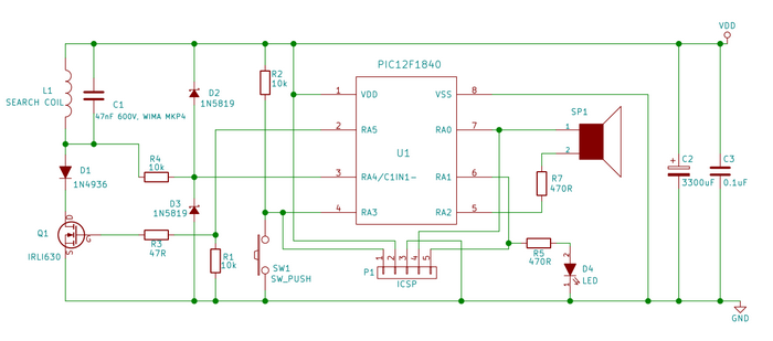
Also, below is the circuit schematic.


Hi Andy,
Here is a link for you. It has a Metal Detector circuit with 12F1840.
Also, below is the circuit schematic.
"If the Earth were a single state, Istanbul would be its capital." Napoleon Bonaparte
 Members who have read this thread : 0
You do not have permission to view the list of names.
 Posting Permissions

Bookmarks