TTL input - 3rd states possible?


Closed Thread
Results 1 to 27 of 27

Hybrid View

  1. #1
    T.Jackson's Avatar
    T.Jackson Guest


    Did you find this post helpful? Yes | No

    Post Valid TTL Levels

    TTL - Transistor-Transistor-Logic, valid logic low between (0 - 0.8v), while valid logic high must be within the region of (2 - 5v) Any where between (0.8 - 2v) may be read as either logic high or low. You can't predict it. Could even oscillate.

    CMOS - Complementary-Metal-Oxide-Semiconductor on the other hand can be feed with up to 26% of VCC for a logic low and a minimum of 73% of VCC for a logic high.

    This industry standard ensures that CMOS is guaranteed to produce no more than 26% of VCC for a low output and no less than 73% of VCC for a high out.

    CMOS is far, far superior to TTL in that it mirror's current from in to out. Some CMOS chips can even partially function even without supply. i.e. if there's something on an input you still get something on an output. TTL is however much more robust. That's the trade off. Plus TTL has a much bigger fanout,
    which means that more inputs can be driven from an output.

    Trent Jackson

  2. #2
    Join Date
    Feb 2005
    Location
    Kolkata-India
    Posts
    563


    Did you find this post helpful? Yes | No

    Default Not tested hastily made after reading post

    Hi,
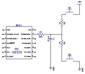
    This is just an idea using the MChip Tips n' Tricks. No timer, no comparator just an idea. Flotulopex please test it out. Others on the forum please comment if it is crap.

    Name:  SWITCH.jpg
Views: 1152
Size:  13.6 KB
    Code:
    READ_SWITCH:
    TRISA.0 = 0             ' MAKE THE PIN AN OUTPUT
    PORTA.0 = 0             ' MAKE IT LOW
    PAUSE 100               ' WAIT FOR THE CAPACITOR TO DISCHARGE 
    
    TRISA.0 = 1             ' MAKE THE PIN AN INPUT
    PAUSE 100               '
    
    IF PORTA.0 = 1 THEN SWITCH_HIGH   '
    
    LED1    = 0             ' DEFINATELY NOT HIGH
    TRISA.0 = 0             ' MAKE THE PIN AN OUTPUT
    PORTA.0 = 1             ' MAKE IT HIGH
    PAUSE 100               '
    
    TRISA.0 = 1             ' MAKE THE PIN AN INPUT
    PAUSE 100               '
    
    IF PORTA.0 = 0 THEN SWITCH_LOW   '
    LED0       = 0          ' DEFINATELY NOT LOW
    
    GOTO READ_SWITCH
    
    SWITCH_LOW:
    LED0 = 1
    GOTO READ_SWITCH
    
    SWITCH_HIGH:
    LED1 = 1
    GOTO READ_SWITCH
    P.S. - The code can be made shorter!!
    Last edited by sougata; - 29th March 2007 at 11:00.
    Regards

    Sougata

  3. #3
    Join Date
    Aug 2006
    Location
    SWITZERLAND (french speaking)
    Posts
    952


    Did you find this post helpful? Yes | No

    Default still blinking

    Hello Sougata,

    Thanks for your code (I copied/pasted it without any change and worked!!!). Unfortunately, the Led0 is still blinking.

    I made a code (also based on the Tips & Tricks) very similar to yours and had the same result.

    As one can multiplex 6 Leds with only 3 pins, I thought I could do something similar with buttons on 1 port.

    After a lots of trials, I think it is not feasable... or I still miss something.

    As already said, I don't care about the Z state. Only both "0" and "1" states would be used.
    Roger

  4. #4
    skimask's Avatar
    skimask Guest


    Did you find this post helpful? Yes | No

    Default

    Quote Originally Posted by flotulopex View Post
    Hello Sougata,
    Thanks for your code (I copied/pasted it without any change and worked!!!). Unfortunately, the Led0 is still blinking.
    I made a code (also based on the Tips & Tricks) very similar to yours and had the same result.
    As one can multiplex 6 Leds with only 3 pins, I thought I could do something similar with buttons on 1 port.
    After a lots of trials, I think it is not feasable... or I still miss something.
    As already said, I don't care about the Z state. Only both "0" and "1" states would be used.
    Curious...why are you worried about the 'Z' state?
    Is it the fact that it can 'hover' around the trip point and cause false readings if left open?

  5. #5
    Join Date
    Feb 2005
    Location
    Kolkata-India
    Posts
    563


    Did you find this post helpful? Yes | No

    Question Time for your schematic and entire code

    Hi,

    It is possible. Did you connect your PIC according to the schematic I provided. <img src="http://www.picbasic.co.uk/forum/attachment.php?attachmentid=1507&d=1175158348" align="absmiddle">Try increasing the pause. Please post your entire code and schematic. It is possible in one way or the other. I have chosen the Digital way. Detecting multiple switches with one pin is also possible using the ADC. By the way the circuit doesn't work when both the switches are pressed simultaneously. The 1K resistors are provided for that purpose so that you don't blow up your PS. When both are pressed most likely your PIC would read a logic high. As you get 1/2VDD and @ 5 volts it is good enough to be a logic 1. In any TTL/CMOS gate your cannot have anything other than 0 or 1 in your output whether your inout is at 0,1 or Z. So software tricks does it. By switching your port pin between input and output and detecting the holding capacitors state. I repeat please post your exact code and schematic and it should work.
    Let me clarify my understanding about your requirement.
    • You need to use only one pin of your PIC.
    • You need to connect 2 switches to that.
    • You need to determine whether your input is hanging idle (Z)
    • Switch connected to VDD was pressed (H)
    • Switch connected to VSS was pressed (L)

    I am waiting.
    Last edited by sougata; - 30th March 2007 at 12:00.
    Regards

    Sougata

  6. #6
    Join Date
    Aug 2006
    Location
    SWITZERLAND (french speaking)
    Posts
    952


    Did you find this post helpful? Yes | No

    Default

    Curious...why are you worried about the 'Z' state?
    ? I don't understand. I said I don't care about the Z state. I would like to read "0" and "1" states (= read two buttons on 1 pin).

    Sougata,

    The code I use is almost the same as yours. I'll post it this evening (I'm in the office now).

    The shematic is absolutely the same as yours but I've some different values:
    PIC16F88-4MHz int osc
    R1 = 10k
    R2/R3=1k2

    Nevertheless, you have pointed out what I was expecting.
    So software tricks does it.
    I'm afraid that reading states that must be defined by software will slow down the maniability of your program.

    In my case, I'm (re)making a SIMON game and when you get use to play with this, you can be quite fast on the buttons.

    I already tried with A/D; this was far to slow. RCTime was to slow too.

    I'll have another try and come back for a feedback.
    Roger

  7. #7
    skimask's Avatar
    skimask Guest


    Did you find this post helpful? Yes | No

    Default

    Ok, now I smell what you're cooking.
    I know you don't care about the 'Z' state, but you probably have to 'worry' about it in this case.
    How about this... when you write to a port, you write the data register, when you read a port, you read the actual pin...so...
    The button's are set up just like in the schematic above.
    You set the pin to an output, and high...read back the pin...
    If it's still high, either the one button pulling it high is pressed or, neither are pressed, if it's low, the other button is pressed...
    Then you set the pin low...read back the pin...
    If it's still low, the one button pulling it low is pressed or, neither are pressed, if it's high, the other button is pressed...
    Problem with this approach is finding a low value to pull the pin far enough (either way) to change states, and yet not smoke the guts of the pin itself.

    pinput var portd.0 : temp var bit : realinput var byte '0=lo, 1=hi, 2=no push
    output pinput : pinput = 1 : temp = pinput
    if temp = 0 then
    realinput = 0 : goto finish
    else
    pinput = 0 : temp = pinput
    if temp = 1 then
    realinput = 1
    else
    realinput = 2 : goto finish
    endif
    endif
    finish: 'done here

    I haven't tried this, might work, might not. If you do go this route, start with high resistor values (10k or so) and work your way down. It'll either start working or smoke the PIC.
    Personally, I like sougata's solution better. If you drop the cap and resistor values, you'll be able to drop the pause values as well, and make everything a lot faster.

Similar Threads

  1. Sony LanC Program
    By l_gaminde in forum Code Examples
    Replies: 2
    Last Post: - 25th September 2009, 19:51
  2. RB0 + Internal Pullup + Interrupt
    By Freman in forum mel PIC BASIC Pro
    Replies: 20
    Last Post: - 10th August 2009, 12:11
  3. LED "capacitance" won't get lower
    By flotulopex in forum mel PIC BASIC Pro
    Replies: 16
    Last Post: - 3rd May 2007, 21:31
  4. Timing input pulses and re-outputting them
    By jamie_s in forum mel PIC BASIC Pro
    Replies: 5
    Last Post: - 28th February 2007, 02:50
  5. Using LEDs as light sensors
    By skimask in forum Code Examples
    Replies: 3
    Last Post: - 30th December 2006, 23:19

Members who have read this thread : 0

You do not have permission to view the list of names.

Posting Permissions

  • You may not post new threads
  • You may not post replies
  • You may not post attachments
  • You may not edit your posts