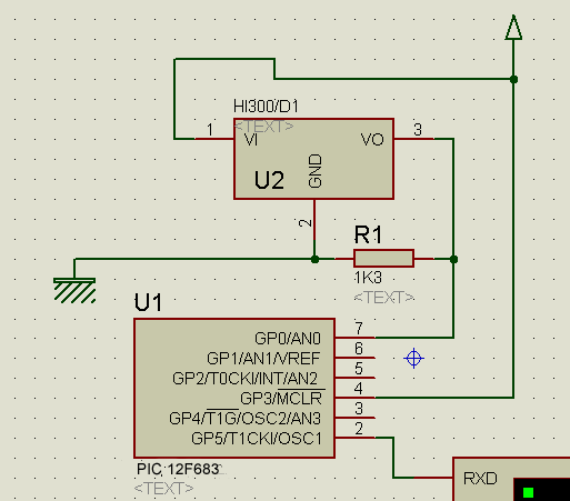
1. It's a hall effect sensor
2. the output is open-collector, the resistor should be to Vdd
3. you need to read a frequency not a voltage
4. read #5 in the features section of the datasheet
1. It's a hall effect sensor
2. the output is open-collector, the resistor should be to Vdd
3. you need to read a frequency not a voltage
4. read #5 in the features section of the datasheet
Steve
It's not a bug, it's a random feature.
There's no problem, only learning opportunities.
Thanks for the prompt reply mister_e.
As you can see im not familiar at all with hall effect sensorsweird thing about the code/schematics I posted is that it somewhat works
I will appreciate any hint on what to do, now that I see the sensor output is digital Im completely lost (pulsin comes to mind)
thanks!
Pulsin may work, Count too, an internal Timer too. I prefer internal timer in counter mode.
Oh BTW, if it was an analog out, you should disable the internal comparator -> CMCON0
Last edited by mister_e; - 3rd October 2006 at 05:20.
Steve
It's not a bug, it's a random feature.
There's no problem, only learning opportunities.
ok timer or pulsin, either way, how do I know when to stop reading and start counting again?
Im reading another hall efect linear sensor datasheet: http://www.allegromicro.com/datafile/1301.pdf this one looks like more appropiate for my code, but it costs 5x the price of the one Im using
back to the HI300/D1, I don't understand how to read it from the datasheet, which by the way looks very brief.
Can you help me with some metacode on how to read this sensor?
thanks
Count PORTB.0,100,ByteVar
This will count the pulse on PORTB.0 during 100mSec
You should measure the frequency at the sensor output first.
Steve
It's not a bug, it's a random feature.
There's no problem, only learning opportunities.
Bookmarks