

I like smiling faces!
Amazing! Thanks.
I have to test them on the new PICs. Wonder whenthey are coming...
Ioannis


I like smiling faces!
Amazing! Thanks.
I have to test them on the new PICs. Wonder whenthey are coming...
Ioannis

Hey Darrel--
I've been trying to reach you re: the consulting I'd hired you to do. I've sent three emails with no response. If you need more money, I'm happy to pay it, and you also have $2200 of my company's equipment... won't you please reply to me?
Thanks--
--Alan McFarland
www.nila.tv

That's just wrong, on so many levels.
I have no Public response. But I will leave this post here.
<br>
DT
Hi,
I want to start my home project to control ventilation fan by time period ON and time period OFF and to use LCD out for interface.
I have just started to write a code in Micro Code studio Plus v.3.0.0.5 with compiler PICBasic PRO v2.50C.
I made a starting (main) interrupt code as a basis for rest algorithm later. It is based on some desired info I have looked on the internet pages. Seems to be workable and started to compile this code. When compiling I have got some results like assembler errors as following:
Error xxx.asm 125[225] undefined symbol 'halfsec'
Error xxx.asm 126[225] undefined symbol 'halfsec'
Error xxx.asm 128[225] undefined symbol 'halfsec'
Error xxx.asm 129[225] undefined symbol 'unsec'
Error xxx.asm 137[225] undefined symbol 'interr'
As for me I can not understand those results at this stage and have no idea what was wrongin my code. Would you be so kind to look at my sourse code and help me to fix this problem in order to continue my project. Thank you inadvance and any ideas are appresiated.
Here is the code example for my project:
@ DEVICE pic16F628A, XT_OSC
@ DEVICE pic16F628A, WDT_ON
@ DEVICE pic16F628A, PWRT_ON
@ DEVICE pic16F628A, MCLR_OFF
@ DEVICE pic16F628A, BOD_ON
@ DEVICE pic16F628A, LVP_OFF
@ DEVICE pic16F628A, CPD_OFF
@ DEVICE pic16F628A, PROTECT_OFF
DEFINE OSC 4
define INTHAND Myint ' Define interrupt handler
counter var word 'to operate with unsec variable in main program
wsave var byte $20 system
ssave var byte bank0 system
psave var byte bank0 system
halfsec var byte
unsec var word
interr var byte
halfsec = 0 'clear the time variables
unsec = 0
interr = 0
INTCON = %11000000 'enable GIE and PEIE
T1CON = %00110101 'Configure TMR1 with clock/4 and prescaler 1/8
PIE1.0 = 1 'enable interrupt TMR1 overflow
goto Main ' Skip around interrupt handler
ASM ; Assembly language interrupt handler
; Save W, STATUS and PCLATH registers
Myint MOVWF wsave
SWAPF STATUS,W
CLRF STATUS
MOVWF ssave
MOVF PCLATH,W
MOVWF psave
; Interrupt code
MOVLW 221
MOVWF TMR1L
MOVLW 11
MOVWF TMR1H
BCF PIR1,0
INC halfsec
BTFSS halfsec,1
GOTO xxx
CLRF halfsec
INC unsec
; Restore PCLATH, STATUS and W registers
xxx MOVF psave,W
MOVWF PCLATH
SWAPF ssave,W
MOVWF STATUS
SWAPF wsave,F
SWAPF wsave,W
BSF interr,0 ;just a flag...
RETFIE
ENDASM
Main: 'Start of the main program
counter = unsec ' Or do something else...
goto Main ' Return to the main program
end ' End
Hi nupass,
welcome to the forum.
First, you really should start a new thread for this as it does not seem to have much to do with this one.
Dave
Always wear safety glasses while programming.
Nupass,
Try putting under scores in front of your variable within the asm routine
halfsec var byte
unsec var word
interr var byte
Asm
_halfsec
_unsec
_interr
endasm
It's in the manual
Dear Mark_S,
Thank you for your welcome, I'am appresiated.
So, I was followed by your suggestion, and put underscore at the beginning of my variables...
... then ... success!!!
It is easier than to make a koffee, just you need some skills... Assembler for me it's a horroble thing...
Well, you have been very helpfull and I have learned some...
Thank you a lot ones again.
To be conitue...
Hi,
I´m not being able to access Darrell´s website to download DT_INTS-14 (I already use INTS-18, which is great, but I´m working on a project which runs on a 16F628A this time). Can someone please attach the latest version of both INTS-14 and INTS-18 to this thread, so people can download even if the site is down?
Thanks!

Here is the latest version 1.00 of DT_INTS-14. The link is to is site, which is back up. http://www.darreltaylor.com/DT_INTS-14/NEW_DT_INTS.zip
More info on above:http://darreltaylor.com/DT_INTS-14/intro2.html
Older version of above:http://darreltaylor.com/DT_INTS-14/intro.html
and here is the latest version of DT_INTS-18 http://www.picbasic.co.uk/forum/showthread.php?p=82871
More info on DTS_INTS-18: http://darreltaylor.com/DT_INTS-18/home.html
Besides the webpages above, this post contains info about the time re-enter takes, which I did not see details of on Darrel's site.
http://www.picbasic.co.uk/forum/show...7587#post17587
Last edited by ScaleRobotics; - 6th February 2010 at 15:40.
Still down for me here in Brazil... Even tried do flush my DNS cache to make sure... Would you be kind enough to attach INTS-14 to your post, so I can continue working?Originally Posted by scalerobotics

Thanks!
Thanks. Now only the only file I still need is elapsed_int-14. Could you please upload that one as well?
Thanks again!
I think the latest version of that is still this one: http://www.picbasic.co.uk/forum/show...7473#post17473
Am I the only one confused by the "ALL_INT -- Global Interrupts" interrupt source?
ALL_INT references the GIE bit (Global Interrupt Enable).
You can use it like this ...
Someone here wanted it, but frankly I think it's easier to just alias the bit, then do GIE = 1.Code:@ INT_ENABLE ALL_INT @ INT_DISABLE ALL_INT
You can not assign a Handler to ALL_INT as an Interrupt Source.
<br>
DT

Darrel,
Thanks for the DT-INTS modules, it's an awesome piece of work. It makes interrupt handling so much easier !
I found this topic because i got stuck using the DT-INTS-18 within code that i was compiling using the 8.43 version of mplab. I got the same error116 over and over again, except when i commented out DT-INTS includes and ASM piece. Microcode studio compiles the exact same code without any error ...
However removing the -K# parameter did the trick, it compiles flawless, exept for the fact that the Mplab SIM can't SIM anymore.
Did you ever discover a workaround or did you get some more info from melabs ?
Best regards,
UB
Yes I did.
See this post for the MPLAB fix.
http://www.picbasic.co.uk/forum/show...26&postcount=3
<br>
DT
wohoo Darrel, Thanks !
Hi Darrel,
I tried this above tip to get back some RAM space to try put my old 12F683 code into a 12F629, but I get a persistent PBP error when I try to compile it.
error[101] d:temp\8chppm~3.asm 450: Error: (ReEnterPBP must be INCLUDEd to use PBP type interrupts)
I also fiddled the wsave value to get past other errors, but this one escapes me, due to not being very familiar with assembly I'd expect.
Heres my ASM code at the start of the program, what did I mess up ?
Thanks Martin
'Interrupt driven 20mS timer for PPM frame timing. See also "my_handler". Uses Timer 1 interrupts.
INCLUDE "DT_INTS-14.bas" ' Base Interrupt System
'INCLUDE "ReEnterPBP.bas" ' Include if using PBP interrupts
ASM
INT_LIST macro ; IntSource, Label, Type, ResetFlag?
INT_Handler TMR1_INT, _my_handler, PBP, yes
endm
INT_CREATE ; Creates the interrupt processor
INT_ENABLE TMR1_INT ; Enable Timer 1 Interrupts
ENDASM
T1CON = $1 ; TMR1ON
'@ INT_ENABLE TMR1_INT ; enable Timer 1 interrupts
error[101] d:temp\8chppm~3.asm 450: Error: (ReEnterPBP must be INCLUDEd to use PBP type interrupts)
'INCLUDE "ReEnterPBP.bas" ' Include if using PBP interrupts
\<-- commented
INT_Handler TMR1_INT, _my_handler, PBP, yes
Ahhh chuew ...
DT

Hi,
I've been trying vary to fully understand the RBC_INT interrupt handler in DT_INTS-18.pbp.
So I wrote this little program, Created a simulator circuit model and also a similar hardware circuit.
Here is the Code:
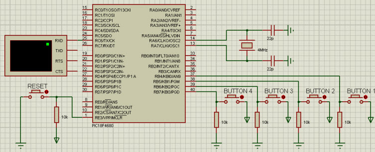
Here is the Circuit:Code:' RBC TEST.BAS ' PIC 18F6480 ' MPLAB IDE V8.40 ' PBP V2.60 ' Build Options: [-ampasmwin] ' RB4 Momentary Contact Button Goes High on Press, 10K Resistor to Ground ' RB5 Momentary Contact Button Goes High on Press, 10K Resistor to Ground ' RB6 Momentary Contact Button Goes High on Press, 10K Resistor to Ground ' RB7 Momentary Contact Button Goes High on Press, 10K Resistor to Ground ' RC6 22K ohm to RX on 57600-N-8-1 Serial Terminal INCLUDE "DT_INTS-18.bas" ; Include Darrel Taylor's Base Interrupt System for PIC18F [Version:3.4 (NOV 04, 2009)] DEFINE OSC 20 DEFINE DEBUG_REG PORTC DEFINE DEBUG_BIT 6 DEFINE DEBUG_BAUD 57600 DEFINE DEBUG_MODE 1 DEFINE SHOWDIGITAL 1 TRISB=%11111111 ADCON0=%00000000 ADCON1=%00001111 BTN VAR BYTE ASM INT_LIST macro ; IntSource, Label, Type, ResetFlag? INT_Handler RBC_INT, _DO_RBC_INT, ASM, yes endm INT_CREATE ENDASM @ INT_ENABLE RBC_INT DEBUG "INTERRUPT CREATED",10,13 DEBUG "INTERRUPT ENABLED",10,13 HOLD_HERE: DEBUG "WAITING FOR INTERRUPT",10,13 PAUSE 2500 GOTO HOLD_HERE DO_RBC_INT DEBUG "############### RBC INTERRUPT ACTIVATED #################",10,13 MENU: PAUSE 200 DEBUG "MENU - READ BUTTONS",10,13 If PORTB.4 = 1 Then PAUSE 250: Goto DO_ENABLE If PORTB.5 = 1 Then PAUSE 250: Goto DO_DISABLE If PORTB.6 = 1 Then PAUSE 250: Goto DO_RETURN If PORTB.7 = 1 Then PAUSE 250: Goto DO_CLEAR GOTO MENU DO_ENABLE: DEBUG "RUNNING DO_ENABLE",10,13 @ INT_ENABLE RBC_INT Pause 250 GOTO HOLD_HERE DO_DISABLE: DEBUG "RUNNING DO_DISABLE",10,13 @ INT_DISABLE RBC_INT PAUSE 250 GOTO HOLD_HERE DO_RETURN: DEBUG "RUNNING DO_RETURN",10,13 @ INT_RETURN PAUSE 250 GOTO HOLD_HERE DO_CLEAR: DEBUG "RUNNING DO_CLEAR",10,13 @ INT_CLEAR RBC_INT PAUSE 250 GOTO HOLD_HERE END
There are 4 buttons connected to PORT B <4.7>
Here are my observations:
The first press of any button activates the RBC Interrupt and sends program to DO_RBC_INT subroutine, then on to MENU where it checks for button presses. This behaves exactly as I would expect it to.
Now...After that....
Pressing Button RB.4 [ENABLE] Runs the DO_ENABLE subroutine then the HOLD_HERE subroutine. At this point, the Interrupt handler seems to shut down as no Port B inputs activate the interrupt handler. I would expect the Interrupt to remain active.
Pressing Button RB.5 [DISABLE] Runs the DO_DISABLE subroutine then the HOLD_HERE subroutine. The Interrupt handler is now disabled as expected.
Pressing Button RB.6 [RETURN] Runs the DO_RETURN subroutine then the HOLD_HERE subroutine. It then sends program to DO_RBC_INT subroutine, then on to MENU. I would expect it to return to HOLD_HERE which is wherr the interrupt was originally activated
Pressing Button RB.7 [CLEAR] Runs the DO_CLEAR subroutine. At this point, the Interrupt handler seems to shut down as no Port B inputs activate the interrupt handler. I would expect this to just clear the interrupt then await another RBC trigger.
So it seems I can only activate the interrupt one time.
It doesn't seem to matter whether I use ASM or PBP types or set Resetflag to yes, or no
Can anyone shed light on what I'm doing wrong, or am I simply misinterpreting the function of the INT_* utilities.
I'm just not sure if I've got a mistake, am staying up too late working on this stuff, or just really don't get it.
Thanks,
Bob
Wozzy-2010
The idea of an Interrupt, is that it Stops the normal flow of the program ... executes an Interrupt Service Routine (ISR) ... then RETURNs back to the same point it was at when it was Interrupted.
You can't go back to the Main Loop without INT_RETURN'ing.
In other words ... no GOTO HOLD_HERE.
<br>
DT
Darrel,
Thanks for the quick reply.
I made a cut & paste error in my last post.
It should have stated:
Pressing Button RB.6 [RETURN] Runs the DO_RETURN subroutine. It then sends program to DO_RBC_INT subroutine, then on to MENU. I would expect it to return to HOLD_HERE which is where the interrupt was originally activated.
Pressing Button RB.7 [CLEAR] Runs the DO_CLEAR subroutine Then the HOLD_HERE. At this point, the Interrupt handler seems to shut down as no Port B inputs activate the interrupt handler. I would expect this to just clear the interrupt then await another RBC trigger.
I agree that it should never get to the GOTO HOLD_HERE statement, at the end of DO_RETURN:, but should still end up in HOLD_HERE since that is where the program was was when the RBC_INT interrupt was initially activated.
Wozzy-2010
Hi,
Sorry Darrel I'm even more confused from the reply. I interpreted your old post and the website info to mean that if I wasn't using PBP interrupts e.g. 'On Interrupt' that I could rem out the ReEnterPBP.bas include. I see I'm interpreting that post wrong.
Can I take that reply to mean that in this case I can't do that, or does this mean I need to write the handler in ASM ?
That's MR Ahhh Cheuw :-)
Hi,
You can use Darrels routines with interrupt service routines written in assembly and/or BASIC. If the interrupt service routines you write are written in BASIC (PBP) you should declare them as type PBP in the INT_LIST AND you must INCLUDE ReEnterPBP.bas. If you write your interrupt service routines in assembly you declare them as Type ASM in in the INT_LIST and then ReEnterPBP file is NOT needed because you're not using ISR's written in BASIC. Anytime one or more of you ISR's are written in BASIC the ReEnterPBP file must be included, only when all handlers are in ASM can it be left out.
ON INTERRUPT is the compilers own way of handling interrupts and has nothing to do with DT_Ints. You use either ON INTERRUPT or Darrels routines.
/Henrik.
Thanks Henrik, that explanation is clear, concise, and fully understood now.
cheers,
Martin
Well I think I've finally figured out some of the nuances of RBC_INT.
I think the last example I tried to use was not a very good way to test it out.
I tried to document this working code example in a way that's understandable and can be used as a template to build on.
This is setup with PBP type interrupts using ReEnterPBP-18.bas, since I'm using PBP in the Interrupt handler, but ... it seems to work just fine when run as ASM type, and not including ReEnterPBP-18.bas. You can just uncomment out the appropriate lines to suit your needs.
The thing that was giving me so much of a headache before was the need to read one of the Port B <4-7> registers prior to exiting the Interrupt handler. This ends the mismatch condition and allows the RB Port Change Interrupt Flag Bit to be cleared. Even though I was reading the Port B <4-7> registers frequently, it seems that using GOTO to enter the Interrupt handler exit subroutine, caused the Interrupt Flag Bit to reset.
Program operation:
This Program uses DEBUG to send status comments to a 9600 Buad Serial ASCII Terminal on PORTC.6
On first press of any of the PORTB<4-7> buttons, the program enters the interrupt handler.
The Interrupt Handler, continuously reads the buttons.
Buttons 1,2 & 3 just display a status message. You could put any subroutine in place of the DEBUG Statement.
Button 4 gracefully exits the interrupt handler.
At this point, RBC_INT is reset and awaiting any PORTB<4-7> button press again to reenter the Interrupt handler.
Anyway here's the Code and a schematic of the setup... I hope this helps someone who's struggling with RBC_INT like I was.
The ZIP file attachment has the code, and copies of the version of DT_INTS-18.bas and ReEnterPBP-18.bas that are included.
Bob W.
Code:' RBC TEST.BAS ' Bob Wozniak ' PIC 18F6480 @ 20 MHZ ' MPLAB IDE V8.40 / PBP V2.60 / Build Options: [-ampasmwin] ' RB4 Momentary Contact Button Goes High on Press, 10K Resistor to Ground ' RB5 Momentary Contact Button Goes High on Press, 10K Resistor to Ground ' RB6 Momentary Contact Button Goes High on Press, 10K Resistor to Ground ' RB7 Momentary Contact Button Goes High on Press, 10K Resistor to Ground ' RC6 22K ohm to RX on 57600-N-8-1 Serial Terminal ' This program created to check Port-B Change Interrupts INCLUDE "DT_INTS-18.bas" ; Include Darrel Taylor's Base Interrupt System for PIC18F [Version:3.4 (NOV 04, 2009)] INCLUDE "ReEnterPBP-18.bas" ; Need to include if using PBP type interrupts DEFINE OSC 20 DEFINE DEBUG_REG PORTC ' SETUP DEBUG to view output on 9600 BAUD ASCII Terminal on PORTC.6 DEFINE DEBUG_BIT 6 DEFINE DEBUG_BAUD 9600 DEFINE DEBUG_MODE 1 I VAR WORD X VAR BYTE ASM INT_LIST macro ; IntSource, Label, Type, ResetFlag? ; INT_Handler RBC_INT, _RBC_INT_HANDLER, ASM, no ; use for ASM type interrupts INT_Handler RBC_INT, _RBC_INT_HANDLER, PBP, no ; use for PBP type interrupts endm INT_CREATE ENDASM @ INT_ENABLE RBC_INT HOLD_HERE: ' **** This subrouting loops continuously and waits for button press to activate RBC interrupt handler IF I = 0 THEN DEBUG 10,13,10,13,"HOLDING FOR PORTB <4-7> BUTTON PRESS to ACTIVATE INTERRUPT",10,13 : I = 1 PAUSE 10 GOTO HOLD_HERE RBC_INT_HANDLER: ' **** Program jumps here when ANY PORTB.4 thru PORTB.7 are changed **** DEBUG "############### RBC INTERRUPT ACTIVATED #################",10,13 PAUSE 250 ' This pause allows time for button debounce - needs to be here unless immediate read of interrupt button req'd READ_BUTTONS: ' **** Program cycles reading buttons, until button 4 is pressed **** If PORTB.4 = 1 Then DEBUG "BUTTON 1 PRESSED",10,13 If PORTB.5 = 1 Then DEBUG "BUTTON 2 PRESSED",10,13 If PORTB.6 = 1 Then DEBUG "BUTTON 3 PRESSED",10,13 If PORTB.7 = 1 Then DEBUG "BUTTON 4 PRESSED - EXITING",10,13 : I = 0 : GOTO END_RBC_INT PAUSE 5 GOTO READ_BUTTONS END_RBC_INT: ' **** this subroutine gracefully exits the interrupt handler and resets for next RBC event **** PAUSE 250 ; This pause allows time for button debounce - needs to be here or interrupt will immediatly reactivate DEBUG "################ EXITING RBC INTERRUPT HANDLER ############",10,13 X = PORTB.7 ; NOTE: Prior to returning from RBC Interrupt, you MUST read at least 1 PORTB <4-7> to end ; the mismatch condition and allow the RB Port Change Interrupt Flag Bit to be cleared. ; If not here, the interrupt will immediatly reactivate if using the GOTO END_RBC_INT statement. @ INT_CLEAR RBC_INT @ INT_ENABLE RBC_INT @ INT_RETURN END
Last edited by WOZZY-2010; - 20th February 2010 at 05:54. Reason: clarify
Wozzy-2010
Hi Bob.
I think you must be very quick on the 4th button to exit (less that 250ms plus the debug delay). If you hold the button longer the ISR will activate again,won't it?
Also the:
@ INT_CLEAR RBC_INT
@ INT_ENABLE RBC_INT
at the end of the ISR are not necessary as they are handled by the DT_Ints, right?
Ioannis
Ioannis...You're right about this. the 250 mS delay is fine on the simulator, but is a little too short to be reliable with real hardware buttons. 400-600 is a better number for use on the hardware.
Thanks for pointing this out...it seems to be somewhat dependent on the value of the DT_INT ResetFlag Here's what I found:
Disabling @ INT_CLEAR RBC_INT
ResetFlag = yes - no change to program operation
ResetFlag = no - Interrupt reactivates again immediately
So the @ INT_CLEAR RBC_INT is dependent on the ResetFlag setting
Disabling @ INT_ENABLE RBC_INT
ResetFlag = yes - no change to program operation
ResetFlag = no - no change to program operation
So the @ INT_ENABLE RBC_INT is not necessary.
I also now realize that I still haven't quite figured out the how INT_DISABLE RBC_INT effects the Interrupt handler in it's different states.
Thanks,
Bob W.
Wozzy-2010
Why do you care so much about Enable/Disable flags? All these are taken care by Darrel in his routines, so normally you don't have to deal with them.
Just do as his examples show and you are OK.
In the extreme case you want some control as to when the interrupts are re-enabled, just use the @INT_ENABLE or @INT_DISABLE commands locally.
Also the simplistic debouncing of a button with time delay is not very elegant and is not recommended as it can delay the program execution.
Ioannis
Ioannis,
I'm really just trying to fully understand this particular interrupt. It's a good learning exercise for me before I go on to other interrupts. I am learning that Darrel's routines are actually much easier to use and sensible than I thought, before I thoroughly confused myself by looking at it in this much detail.
As I'm really pretty new to this, I'd be very interested to know what is your recommendation for debouncing. Are you talking about a hardware, or a software solution?
For my current application, the interrupt is just used to jump out of the main program to enter a set up menu. So the main program is on hold and nothing is time critical. This whole RBC_INT study is just a tangent that I went off on, when I didn't understand why the stuff that I had cut & paste from the examples didn't behave as I expected.
Thanks again,
Bob W.
Wozzy-2010
Well, the idea is to use the interrupts, both with Port Interrupt on Change and Timer.
On the first interrupt from your button, you start the timer. If you have multiple interrupts from the same button and the timer stil runs, just drop them.
If the timer interrupt occurs, and the button is still pressed, then you can confirm that is really pressed, setting a flag.
Hope this helps a little.
Ioannis
I have a small test board that has an ICSP and a USB connection to a pic 18f4550. I have a reset button on the MCLR and a second button on portb.1. An led is connected to portb.0
The ICSP is used to program a bootloader onto the chip. Then USB is used to add the user program.
I have loaded the Diolan bootloader onto this chip and it is working.
I can make a test program in PBP 2.6 that flashes the LED on port b.0
like this: The Bootloader required code to start at 0x800
The above program works as expected. So the next step was to try the DT_INTS-18 with the bootloader...the code appears to load into the PIC fine, but after reset there is a pause of about 5 seconds then the chip shows up as an un-recognized USB device but does not enter the bootloader mode. To enter bootloader mode the PB on portb.1 is held down during power-on/reset. OR the user application can branch to 0x0016.Code:DEFINE OSC 48 DEFINE RESET_ORG 0x800 ' Example program to blink an LED connected to PORTB.0 about ' once a second Main: High 0 ' Turn on LED connected to PORTB.0 Pause 500 ' Delay for .5 seconds Low 0 ' Turn off LED connected to PORTB.0 Pause 500 ' Delay for .5 seconds Goto Main ' Go back to loop and blink LED forever End
It appears the program is branching somewhere to restart the bootloader code since the pic shows up as an unrecognized USB device. It should not show up at all after the code is loaded since I don't have any usb code in the user app listed below.
Here is my test program with the DT_INTS-18 that is not working...
Code:DEFINE OSC 20 DEFINE RESET_ORG 0x800 INCLUDE "DT_INTS-18.bas" ' Base Interrupt System INCLUDE "ReEnterPBP-18.bas" ' Include if using PBP interrupts LED1 VAR PORTB.0 ASM INT_LIST macro ; IntSource, Label, Type, ResetFlag? INT_Handler TMR1_INT, _ToggleLED1, PBP, yes endm INT_CREATE ; Creates the interrupt processor ENDASM T1CON = $31 ; Prescaler = 8, TMR1ON @ INT_ENABLE TMR1_INT ; enable Timer 1 interrupts Main: PAUSE 1 GOTO Main '---[TMR1 - interrupt handler]-------------------------------------------------- ToggleLED1: TOGGLE LED1 @ INT_RETURN
Any thoughts on why it's not blinking the led using the DT_INTS-18 code and running off into la la land?
ADDED: I am using the MPASM assembler as well.
Thanks
Tom
Last edited by vamtbrider; - 25th March 2010 at 19:28. Reason: Added Assembler info
I added the port configuration and acon register configs. That has an effect...
The bootloader never leaves the bootloader mode to run the user app.
if I comment out the Hardware configuration section and compile I can load the code via the bootloader, the device disappears from the USB list and then ~10seconds later I get the USB device not recognized.
I have reloaded the led test program just to make sure the bootloader and chip are still working and they are. Very puzzling, but the registers do seem to have an effect.
Nothing in the DT_INT writes to EEPROM 0x00? If there is a 5A there then the bootloader thinks its still in boot mode.
Still puzzled...Code:LED1 VAR PORTB.0 DEFINE OSC 20 DEFINE RESET_ORG 0x800 INCLUDE "DT_INTS-18.bas" ' Base Interrupt System INCLUDE "ReEnterPBP-18.bas" ' Include if using PBP interrupts ' Hardware configuration ' ====================== ' ' I/O and PORTs ' ------------- PORTB = 0 PORTC = 0 PORTD = 0 PORTE = 0 TRISB = %00000000 '<2-1> Inputs TRISC = 0 TRISA = 0 TRISD = 0 TRISE = 0 ' ' A/D converter ' ------------- ADCON0 = %00000000 ' A/D converter off ADCON1 = %00001111 ' All Digital Inputs ' ADCON2 = %00000000 ASM INT_LIST macro ; IntSource, Label, Type, ResetFlag? INT_Handler TMR1_INT, _ToggleLED1, PBP, yes endm INT_CREATE ; Creates the interrupt processor ENDASM T1CON = $31 ; Prescaler = 8, TMR1ON @ INT_ENABLE TMR1_INT ; enable Timer 1 interrupts Main: Pause 10 GOTO Main '---[TMR1 - interrupt handler]-------------------------------------------------- ToggleLED1: TOGGLE LED1 @ INT_RETURN
This hardware config give the same results as the original issue...ie the LED does not blink and the code appears to run off into la la land. Not sure how it is being detected as a usb device with the DT_INTS-18 code.
I have two port b pins connected together as part of the ICSP and 2 others connected for inputs off a single PB. Setting the TRISB to FE is what got me back to the original problem.Code:' Hardware configuration ' ====================== ' ' I/O and PORTs ' ------------- PORTB = 0 PORTC = 0 PORTD = 0 PORTE = 0 TRISB = %11111110 '<7:1> Inputs TRISC = 0 TRISA = 0 TRISD = 0 TRISE = 0 ' ' A/D converter ' ------------- ADCON0 = %00000000 ' A/D converter off ADCON1 = %00001111 ' All Digital Inputs ADCON2 = %00000000
I've never used this loader, but I did take a quick peek at the source files.
Try this;
Remove power. Place a jumper from PORTE.0 to ground. Power up & load the above after compiling it.Code:DEFINE OSC 20 DEFINE RESET_ORG 0x800 INCLUDE "DT_INTS-18.bas" ' Base Interrupt System INCLUDE "ReEnterPBP-18.bas" ' Include if using PBP interrupts LED1 VAR PORTB.0 ' Hardware configuration ' ====================== ADCON1 = %00001111 ' All Digital Inputs ASM INT_LIST macro ; IntSource, Label, Type, ResetFlag? INT_Handler TMR1_INT, _ToggleLED1, PBP, yes endm INT_CREATE ; Creates the interrupt processor ENDASM T1CON = $31 ; Prescaler = 8, TMR1ON @ INT_ENABLE TMR1_INT ; enable Timer 1 interrupts Main: Pause 10 GOTO Main '---[TMR1 - interrupt handler]-------------------------------------------------- ToggleLED1: TOGGLE LED1 @ INT_RETURN
After programming it with the loader, power down. Move the jumper on PORTE.0 to Vcc, and power up.
Does it work now?
If I don't have the TRISB config the bootloader never enters the user program mode.
I added the TRISB = %1111110 and it enters the user program but still shows an undetected USB device after a few seconds and the LED on PORTB.0 is still not blinking.
One more piece of info, I am getting power from the USB port on my laptop. Even though the user program is not using USB I am "stealing" power for this test setup from the USB port. i.e. I download the program to the bootloader through the PIC USB and leave the cable connected to power the board for testing.
It doesn't look like anything in the DT_INTS would be triggered from activity on the USB port since I have not explicitly configured the USB_INT. The PIC is certainly seeing a request from the PC since its connected to the PIC circuitry and that could be why I get the USB device not recognized...although I don't get that when i am running just the Blink program using PAUSE 500 statements.
When I get home later tonight I will load this program directly on the PIC through the ICSP without the bootloader to verify my setup is happy. Then I will try the bootloader again and use an external power supply instead of the USB power.
ADDED: I have reconfigured the Bootloader to use PORT B.1 instead of Diolan's default of PortE.0. My end application will use Port B.1 so I built this test board assuming portb.1 would work.
Last edited by vamtbrider; - 25th March 2010 at 21:53. Reason: Added Bootloader Jumper Information
Try adding ...
Code:DEFINE LOADER_USED 1
DT
Pheeeewwww! I do NOT like that loader at all.
I put one together for you here using the Microchip USB HID boot-loader. Give this one a shot. It works 100% with DT_INTS-18.
I modified the original C18 loader file so you can switch between the external crystal & internal osc at run-time to switch back-and-forth to various speeds.
Use a 20MHz crystal, 18F4550, and you should have no problems at all with the loader or DT_INTS-18.
Of course you'll need to download & install the Microchip HID USB loader PC app, but I find that one WAY nicer, and easier to use than the Diolan thing.
Some day when I have time I might figure the other one out, but this took a fraction of the time to change & test.Code:'**************************************************************** '* Name : USB_TST.BAS * '* Author : B. Reynolds * '* Notice : Copyright (c) 2010 http://www.Rentron.com * '* : All Rights Reserved * '* Date : 3/25/2010 * '* Version : 1.0 * '* Notes : Using the Microchip USB HID Boot-Loader with PBP * '* : and DT_INTS. * '**************************************************************** ' Using the Microchip MCHPFSUSB v2.1 HID USB Bootloader with PBP & DT INTS. ' Place a 10K pull-up on RB4 with a switch to ground RB4 when pressed. ' Loader mode. Press & hold switch on RB4, then press/release reset switch on /MCLR. ' Now release switch on RB4. ' LEDs on PORTD.0 & D.1 will blink on/off quickly showiing you're in loader mode ' and the MCHPFSUSB v2.1 HID PC bootloader software should now recognize your board. ' Open & load your compiled code, with the loader software, then press/release ' the switch on /MCLR, or click Reset Device on the loader software. ' Your code should now be running. DEFINE OSC 48 ' Loader configured for 20MHz OSC on USB board DEFINE RESET_ORG 0x1000 ' User code start location for HID loader INCLUDE "DT_INTS-18.bas" ' Base Interrupt System INCLUDE "ReEnterPBP-18.bas" ' Include if using PBP interrupts LED1 VAR PORTD.0 Loops VAR BYTE ' Hardware configuration ' ====================== ADCON1 = %00001111 ' All Digital ASM INT_LIST macro ; IntSource, Label, Type, ResetFlag? INT_Handler TMR1_INT, _ToggleLED1, PBP, yes endm INT_CREATE ; Creates the interrupt processor ENDASM T1CON = $31 ; Prescaler = 8, TMR1ON @ INT_ENABLE TMR1_INT ; Enable Timer 1 interrupts OSCCON = %01110000 ; Switch to internal whenever you want by just ; flipping OSCCON.1 to 1. ; To run at 48MHz, flip OSCCON.1 back to 0.. Main: FOR Loops = 1 TO 6 ' we'll run at 48MHz here TOGGLE PORTD.1 Pause 500 NEXT Loops OSCCON.1 = 1 ' we'll run at 8MHz on internal osc here FOR Loops = 1 TO 6 TOGGLE PORTD.1 Pause 500 NEXT Loops OSCCON.1 = 0 ' flip switch back to 48MHz GOTO Main '---[TMR1 - interrupt handler]-------------------------------------------------- ToggleLED1: TOGGLE LED1 @ INT_RETURN END
I think I have two problems.
One the jumper for bootloader mode is a PB that will tie portb.1 and 2 to ground when pressed. Walking through the bootloader code with the MPLAB debugger the portb inputs are not always on. Some times they are and sometimes they are not. I enabled the pull ups through the INCON2<7> but that doesn't seem to help. So I need to figure that out first.
A few times I have been able to get the DT_INTS-18 code with the blinky light to load into the PIC via the bootloader while still in debug mode in MPLABS. This has lead to the second problem.
When the interrupt comes in the code jumps to 0x008 which has a GOTO 0x808.
At 0x808 is another GOTO 0x998
running through the interrupt eventually gets to the code below:
the program resets after executing the instruction at 08F4 - MOVWF PCL, ACCESS. It looks like the WREG has a value of 0xDC that it is trying to stuff into PCL.Code:1122 08C2 C017 MOVFF usb_sm_state, 0x90 1123 08C4 F090 NOP 1124 08C6 C018 MOVFF usb_sm_ctrl_state, 0x91 1125 08C8 F091 NOP 1126 08CA C019 MOVFF usb_active_cfg, 0x92 1127 08CC F092 NOP 1128 08CE C01A MOVFF usb_alt_intf, 0x93 1129 08D0 F093 NOP 1130 08D2 8022 BSF [0x22], 0 1131 08D4 B414 BTFSC [0x14], 0x2 1132 08D6 EF74 GOTO 0x8e8 1133 08D8 F004 NOP 1134 08DA C021 MOVFF 0x21, PCLATU 1135 08DC FFFB NOP 1136 08DE C020 MOVFF 0x20, PCLATH 1137 08E0 FFFA NOP 1138 08E2 501F MOVF [0x1f], W 1139 08E4 6AE0 CLRF BSR, ACCESS 1140 08E6 6EF9 MOVWF PCL, ACCESS 1141 08E8 C01E MOVFF pSrc, PCLATU 1142 08EA FFFB NOP 1143 08EC C01D MOVFF 0x1d, PCLATH 1144 08EE FFFA NOP 1145 08F0 501C MOVF [0x1c], W 1146 08F2 6AE0 CLRF BSR, ACCESS 1147 08F4 6EF9 MOVWF PCL, ACCESS 1148 08F6 0004 CLRWDT 1149 08F8 A022 BTFSS [0x22], 0 1150 08FA EFB4 GOTO 0x968
Basically the debugger stops stepping at that line, I click on the next line below it and select run to cursor the code restarts at 0x00. The bootloader checks the jumper, which is not there and then runs the app.
So basically it looks like the code keeps running to the first interrupt and then resetting the PIC.
I have attached a capture of the PIC Program Memory for what its worth.
I also loaded just the DT_INTS blinky light program onto the PIC without the bootloader. Using the MPLABS debugger i am able to see that when the code gets to the MOVWF PCL, ACCESS instruction it moves 0x34 from WREG into the PCL and the program jumps to 0x0234. The code at 0x0234 looks like the TOGGLELED1: code to actually toggle port b.0.
The code runs great without the bootloader.
Comparing the two pieces of code it looks like the bootloader version should be branching to 0x9DC...but instead I think its running off the stack and resetting the PIC.
I am now going to try and reload the DT_INTS with the bootloader and see if I can capture the PCL, PCLATH and PCLATU registers when the code attempts to move 0xDC into PCL. Hopefully I can see where it is really trying to go.
Its kind of late here in VA so I may have to tackle this tomorrow night.
Thanks for all the ideas so far.
Tom
 Members who have read this thread : 5
You do not have permission to view the list of names.
 Posting Permissions


Bookmarks