
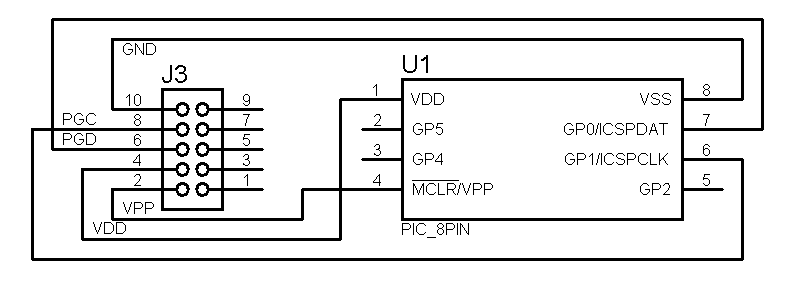
There are 5 wires on that clip.
But if your circuit is powered externally, you don't need VDD.


There are 5 wires on that clip.
But if your circuit is powered externally, you don't need VDD.
DT
 Members who have read this thread : 0
You do not have permission to view the list of names.
 Posting Permissions

Bookmarks