Code:
#config
CONFIG RETEN = OFF
CONFIG INTOSCSEL = HIGH
CONFIG SOSCSEL = DIG
CONFIG XINST = OFF	    ;Enabled
CONFIG FOSC = INTIO1
CONFIG PLLCFG = OFF
CONFIG FCMEN = OFF	    ;Disabled
CONFIG PWRTEN = OFF	    ;Disabled
CONFIG BOREN = OFF	    ;Disabled in hardware, SBOREN disabled
CONFIG WDTEN = OFF	    ;WDT disabled in hardware; SWDTEN bit disabled
CONFIG CANMX = PORTB
CONFIG MCLRE = OFF


#endconfig


OSCTUNE.6 = 1 ; Enable 4x PLL
OSCCON = %01110000
ANCON1=0 'DISABLE ADC D3-D2-D1-D0-   b
ANCON0=%00000000                      'a
ADCON0=0
ADCON1=%11110000
TRISC=%00000000 'set PORTC as output all
TRISD=%00000000 'set PORTD as output all
TRISB=%00000000 'set PORTB as output all
TRISA=%00000000 'set PORTA as output all
TRISE=%00000000 'set PORTE as output all
define OSC 64


SCL_PIN VAR PORTC.0   ' I2C clock pin
SDA_PIN VAR PORTC.1   ' I2C data pin


PCA9685_CTRL_W CON $80   ' 8-bit write control byte
MODE1_REG      CON $00
MODE2_REG      CON $01
PRE_SCALE_REG  CON $FE
LED0_ON_L      CON $06


channel VAR BYTE          ' <-- define channel variable


' ----- Initialization -----
' Put device to sleep to set prescale
I2CWRITE SDA_PIN, SCL_PIN, PCA9685_CTRL_W, MODE1_REG, [$10]   ' SLEEP=1
PAUSE 5


' Set prescale for ~1 kHz PWM (example value)
I2CWRITE SDA_PIN, SCL_PIN, PCA9685_CTRL_W, PRE_SCALE_REG, [$06]


' Wake up, enable auto-increment
I2CWRITE SDA_PIN, SCL_PIN, PCA9685_CTRL_W, MODE1_REG, [$20]   ' AI=1, SLEEP=0
PAUSE 5


' Set outputs inverted + totem-pole
I2CWRITE SDA_PIN, SCL_PIN, PCA9685_CTRL_W, MODE2_REG, [$14]


' Force all channels full-off (outputs HIGH, LEDs off)
FOR channel = 0 TO 15
    I2CWRITE SDA_PIN, SCL_PIN, PCA9685_CTRL_W, (LED0_ON_L + channel*4), [$00,$00,$00,$10]
NEXT channel
PAUSE 10


' ----- Main loop -----
MainLoop:
    FOR channel = 2 TO 5
        ' Turn channel fully ON (use "full on": ON_H bit4 = 1)
        I2CWRITE SDA_PIN, SCL_PIN, PCA9685_CTRL_W, (LED0_ON_L + channel*4), [$00,$10,$00,$00]
        PAUSE 500


        ' Turn channel OFF again (full off: OFF_H bit4 = 1)
        I2CWRITE SDA_PIN, SCL_PIN, PCA9685_CTRL_W, (LED0_ON_L + channel*4), [$00,$00,$00,$10]
        PAUSE 200
    NEXT channel
GOTO MainLoop
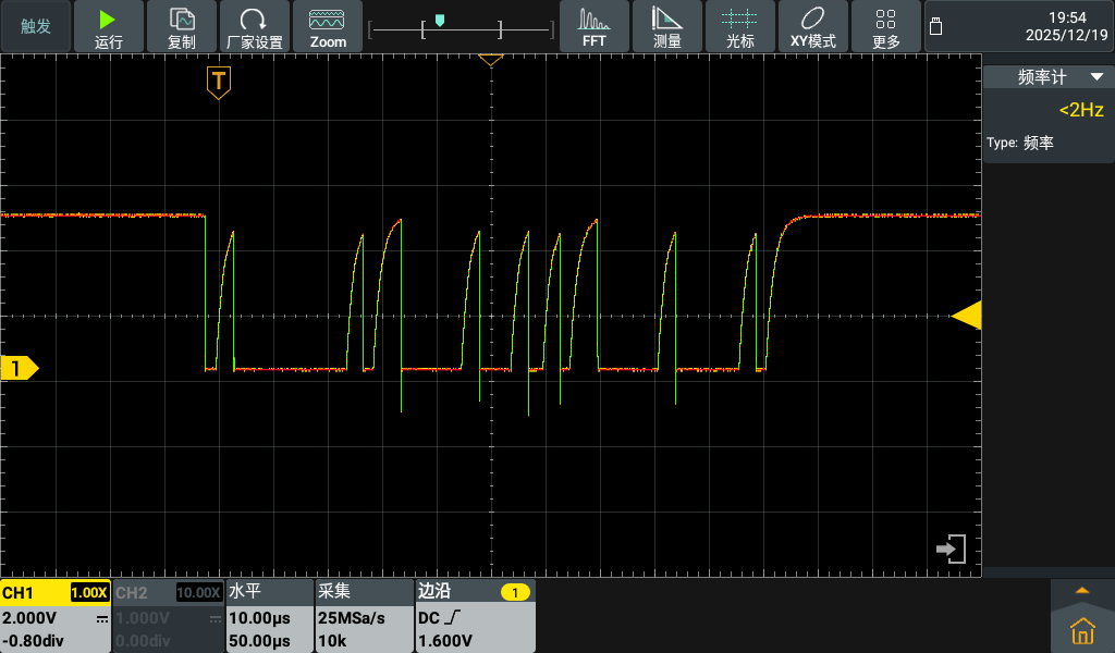
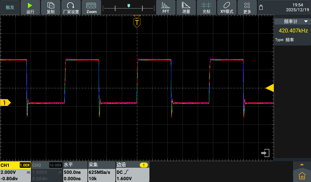
I decided to check the signals with scope, and they're heavily distorted. (image 1) I have 10K pull-up resistors on both SDA and SCL pin. So to test the issues, I've added this simple code:


 Reply With Quote


Bookmarks