Losing data when extracting bytes from words - 16F18855


+ Reply to Thread
Results 1 to 26 of 26

Hybrid View

  1. #1
    Join Date
    Jan 2005
    Location
    Montreal, Quebec, Canada
    Posts
    3,154

    Question Losing data when extracting bytes from words - 16F18855

    I haven't figured out a pattern. I went all the way up to 1999 and it's always the same ones that mess up, starting with 93-99.

    Transmit code using only 0-99, will wait for OK signal back from RX PIC before sending another set:

    Code:
    #CONFIG
        __config _CONFIG1, _FEXTOSC_OFF & _RSTOSC_HFINT32 & _CLKOUTEN_OFF & _CSWEN_OFF & _FCMEN_ON
        __config _CONFIG2, _MCLRE_ON & _PWRTE_OFF & _LPBOREN_OFF & _BOREN_ON & _BORV_LO & _ZCD_OFF & _PPS1WAY_OFF & _STVREN_ON & _DEBUG_OFF
        __config _CONFIG3, _WDTCPS_WDTCPS_11 & _WDTE_OFF & _WDTCWS_WDTCWS_7 & _WDTCCS_LFINTOSC
        __config _CONFIG4, _WRT_OFF & _SCANE_available & _LVP_OFF
        __config _CONFIG5, _CP_OFF & _CPD_OFF
    #ENDCONFIG
    DEFINE OSC 32
    DEFINE  HSER_RXREG PORTC
    DEFINE  HSER_RXBIT 7
    DEFINE  HSER_TXREG PORTC
    DEFINE  HSER_TXBIT 6
    DEFINE  HSER_RCSTA 90h              ' Enable serial port & continuous receive
    DEFINE  HSER_TXSTA 24h              ' Enable transmit, BRGH = 1
    Define  HSER_BAUD 115200
    DEFINE  HSER_CLROERR 1              ' Clear overflow automatically
    DEFINE  HSER_SPBRGH  0
    DEFINE  HSER_SPBRG  68
    BAUDCON.3 = 1                       ' Enable 16 bit baudrate generator
    WPUA = %11111111
    WPUB = %11111111
    WPUC = %00111111
    ANSELA = %00000000
    ANSELB = %00000000
    ANSELC = %00000000
    TRISA = %00000000
    TRISB = %00000000
    TRISC = %11000000
    MsgData             var byte[21]
    MsgOK               var byte[2]
    MsgLoop             VAR WORD
    Num0                VAR WORD
    Num1                VAR WORD
    Num2                VAR WORD
    Num3                VAR WORD
    Num4                VAR WORD
    Num5                VAR WORD
    Num6                VAR WORD
    Num7                VAR WORD
    Num8                VAR WORD
    Num9                VAR WORD
    ADCcode             var BYTE
    
        Pause 1000                           ' Let PIC stabilize and start after RX PIC
    
    goto mainloop
    
    TransmitData:
    
        Num0 = MsgLoop
        Num1 = MsgLoop + 1
        Num2 = MsgLoop + 2
        Num3 = MsgLoop + 3
        Num4 = MsgLoop + 4
        Num5 = MsgLoop + 5
        Num6 = MsgLoop + 6
        Num7 = MsgLoop + 7
        Num8 = MsgLoop + 8
        Num9 = MsgLoop + 9
    
        MsgData[1] = Num0.byte1 : MsgData[2] = Num0.byte0
        MsgData[3] = num1.byte1 : MsgData[4] = num1.byte0
        MsgData[5] = num2.byte1 : MsgData[6] = num2.byte0
        MsgData[7] = num3.byte1 : MsgData[8] = num3.byte0
        MsgData[9] = num4.byte1 : MsgData[10] = num4.byte0
        MsgData[11] = num5.byte1 : MsgData[12] = num5.byte0
        MsgData[13] = num6.byte1 : MsgData[14] = num6.byte0
        MsgData[15] = num7.byte1 : MsgData[16] = num7.byte0
        MsgData[17] = num8.byte1 : MsgData[18] = num8.byte0
        MsgData[19] = num9.byte1 : MsgData[20] = num9.byte0
    
        hserout [   "[", ADCcode, _
                    MsgData[1],  MsgData[2],  MsgData[3],  MsgData[4],  MsgData[5],  _
                    MsgData[6],  MsgData[7],  MsgData[8],  MsgData[9],  MsgData[10], _                             
                    MsgData[11],  MsgData[12],  MsgData[13],  MsgData[14],  MsgData[15], _                            
                    MsgData[16],  MsgData[17],  MsgData[18],  MsgData[19],  MsgData[20], "]"]                             
        while TXSTA.1 = 0               ' Check TRMT bit
        wend
    RETURN
    
    Mainloop:
    
        ADCcode = 2
        for MsgLoop = 0 to 90 step 10                         ' loop by multiples of 10
            gosub TransmitData
            hserin [ wait("<"), STR MsgOK\2\">" ]               ' return confirmation code
        next MsgLoop
    end

    RX code (stripped of LCD code):

    Code:
    #CONFIG
        __config _CONFIG1, _FEXTOSC_OFF & _RSTOSC_HFINT32 & _CLKOUTEN_OFF & _CSWEN_OFF & _FCMEN_ON
        __config _CONFIG2, _MCLRE_ON & _PWRTE_OFF & _LPBOREN_OFF & _BOREN_ON & _BORV_LO & _ZCD_OFF & _PPS1WAY_OFF & _STVREN_ON & _DEBUG_OFF
        __config _CONFIG3, _WDTCPS_WDTCPS_11 & _WDTE_OFF & _WDTCWS_WDTCWS_7 & _WDTCCS_LFINTOSC
        __config _CONFIG4, _WRT_OFF & _SCANE_available & _LVP_OFF
        __config _CONFIG5, _CP_OFF & _CPD_OFF
    #ENDCONFIG
    DEFINE OSC 32
    DEFINE  HSER_RXREG PORTC
    DEFINE  HSER_RXBIT 7
    DEFINE  HSER_TXREG PORTC
    DEFINE  HSER_TXBIT 6
    DEFINE  HSER_RCSTA 90h              ' Enable serial port & continuous receive
    DEFINE  HSER_TXSTA 24h              ' Enable transmit, BRGH = 1
    Define  HSER_BAUD 115200
    DEFINE  HSER_CLROERR 1              ' Clear overflow automatically
    DEFINE  HSER_SPBRGH  0
    DEFINE  HSER_SPBRG  68
    BAUDCON.3 = 1                       ' Enable 16 bit baudrate generator
    WPUA = %11111111
    WPUB = %11111111
    WPUC = %00111111
    ANSELA = %00000000
    ANSELB = %00000000
    ANSELC = %00000000
    TRISA = %00000000
    TRISB = %00000000                   ' B6 - ICSPCLK
                                        ' B7 - ICSPDAT
    TRISC = %11000000                   ' C6 - HSEROUT
                                        ' C7 - HSERIN
    MsgData             var byte[21]
    Num0                VAR WORD
    Num1                VAR WORD
    Num2                VAR WORD
    Num3                VAR WORD
    Num4                VAR WORD
    Num5                VAR WORD
    Num6                VAR WORD
    Num7                VAR WORD
    Num8                VAR WORD
    Num9                VAR WORD
        Pause 200                           ' Let PIC and LCD stabilize
        
    Mainloop:
      
        hserin [ wait("["), STR MsgData\21\"]" ]
    
        if MsgData[0] = 2 then
            Num0.byte1 = MsgData[1] : Num0.byte0 = MsgData[2]
            Num1.byte1 = MsgData[3] : Num1.byte0 = MsgData[4]
            Num2.byte1 = MsgData[5] : Num2.byte0 = MsgData[6]
            Num3.byte1 = MsgData[7] : Num3.byte0 = MsgData[8]
            Num4.byte1 = MsgData[9] : Num4.byte0 = MsgData[10]
            Num5.byte1 = MsgData[11] : Num5.byte0 = MsgData[12]
            Num6.byte1 = MsgData[13] : Num6.byte0 = MsgData[14]
            Num7.byte1 = MsgData[15] : Num7.byte0 = MsgData[16]
            Num8.byte1 = MsgData[17] : Num8.byte0 = MsgData[18]
            Num9.byte1 = MsgData[19] : Num9.byte0 = MsgData[20]
    
            hserout [   "[", dec4 Num0, _
                        " ", dec4 Num1, " ", dec4 Num2, " ", dec4 Num3, _
                        " ", dec4 Num4, " ", dec4 Num5, " ", dec4 Num6, _
                        " ", dec4 Num7, " ", dec4 Num8, " ", dec4 Num9, "]"]                             
            while TXSTA.1 = 0               ' Check TRMT bit
            wend
    
            hserout [   "<OK>"]             ' MAKE SURE DATA IS COMPLETELY SENT BEFORE CONFIRMATION                             
            hserout [   10]                 ' this is just to maintain alignment on Serial Communicator            
        endif
    
      GOTO Mainloop
    end

    Output from RX program to MCS+ Serial Communicator:

    Code:
    [0000 0001 0002 0003 0004 0005 0006 0007 0008 0009]<OK>
    [0010 0011 0012 0013 0014 0015 0016 0017 0018 0019]<OK>
    [0020 0021 0022 0023 0024 0025 0026 0027 0028 0029]<OK>
    [0030 0031 0032 0033 0034 0035 0036 0037 0038 0039]<OK>
    [0040 0041 0042 0043 0044 0045 0046 0047 0048 0049]<OK>
    [0050 0051 0052 0053 0054 0055 0056 0057 0058 0059]<OK>
    [0060 0061 0062 0063 0064 0065 0066 0067 0068 0069]<OK>
    [0070 0071 0072 0073 0074 0075 0076 0077 0078 0079]<OK>
    [0080 0081 0082 0083 0084 0085 0086 0087 0088 0089]<OK>
    [0090 0091 0092 0000 0000 0000 0000 0000 0000 0000]<OK>

    I know it's transmitted properly using Saleae probe:

    Name:  Missing HSEROUT v3.png
Views: 824
Size:  22.1 KB


    The data is complete on top row (RX from TX PIC), but missing on bottom (TX towards PC).
    My Creality Ender 3 S1 Plus is a giant paperweight that can't even be used as a boat anchor, cause I'd be fined for polluting our waterways with electronic devices.

    Not as dumb as yesterday, but stupider than tomorrow!

  2. #2
    Join Date
    Jan 2005
    Location
    Montreal, Quebec, Canada
    Posts
    3,154


    Did you find this post helpful? Yes | No

    Default Re: Losing data when extracting bytes from words

    This is when I run it up to 1990, and repeat the 90 series at the bottom; always the same numbers are messed up.

    Missing HSEROUT v4.pdf
    My Creality Ender 3 S1 Plus is a giant paperweight that can't even be used as a boat anchor, cause I'd be fined for polluting our waterways with electronic devices.

    Not as dumb as yesterday, but stupider than tomorrow!

  3. #3
    Join Date
    Jan 2005
    Location
    Montreal, Quebec, Canada
    Posts
    3,154


    Did you find this post helpful? Yes | No

    Default Re: Losing data when extracting bytes from words

    I just noticed something. It didn't wait for the 90 series to complete.

    Something is not always working with my OK reply.

    Name:  Missing HSEROUT v4.png
Views: 657
Size:  46.1 KB


    EDIT: Confirmed, I checked the longest saved SALEAE session. All the series that are chopped are missing numbers that relate with how early the TX started on the RX PIC. It didn't wait for the HSERIN to complete, and took off running.

    I can't explain why it's always the same series.


    Something tells me the DEFINES are different for this PIC, and I blindly copied over existing code.
    Last edited by Demon; - 7th March 2025 at 02:47.
    My Creality Ender 3 S1 Plus is a giant paperweight that can't even be used as a boat anchor, cause I'd be fined for polluting our waterways with electronic devices.

    Not as dumb as yesterday, but stupider than tomorrow!

  4. #4
    Join Date
    May 2013
    Location
    australia
    Posts
    2,631


    Did you find this post helpful? Yes | No

    Default Re: Losing data when extracting bytes from words - 16F18855

    You will notice you never receive the data from 93 onwards

    since your terminator is "]" <==> ascii 93
    Warning I'm not a teacher

  5. #5
    Join Date
    Jan 2005
    Location
    Montreal, Quebec, Canada
    Posts
    3,154


    Did you find this post helpful? Yes | No

    Default Re: Losing data when extracting bytes from words - 16F18855

    Quote Originally Posted by richard View Post
    You will notice you never receive the data from 93 onwards

    since your terminator is "]" <==> ascii 93

    Ok, but what about these guys?

    Code:
    [0340 0341 0342 0343 0344 0345 0346 0347 0348 0256]
    [0860 0768 0000 0000 0000 0000 0000 0000 0000 0000]
    [1110 1111 1112 1113 1114 1115 1116 1024 0000 0000]
    [1620 1621 1622 1623 1624 1625 1626 1627 1628 1536]
    [1880 1881 1882 1883 1884 1792 0000 0000 0000 0000]        <---- this one does have a 93

    EDIT: What would you suggest as a good delimiter? I have no idea what would avoid this stuff.
    Last edited by Demon; - 7th March 2025 at 03:54.
    My Creality Ender 3 S1 Plus is a giant paperweight that can't even be used as a boat anchor, cause I'd be fined for polluting our waterways with electronic devices.

    Not as dumb as yesterday, but stupider than tomorrow!

  6. #6
    Join Date
    May 2013
    Location
    australia
    Posts
    2,631


    Did you find this post helpful? Yes | No

    Default Re: Losing data when extracting bytes from words - 16F18855

    349 dec = 0x15d 0x5d = dec 93 <==> ascii "]"
    Warning I'm not a teacher

  7. #7
    Join Date
    May 2013
    Location
    australia
    Posts
    2,631


    Did you find this post helpful? Yes | No

    Default Re: Losing data when extracting bytes from words - 16F18855

    delimiters only works for ascii data , converting data to from ascii is a slow ugly process that bloats the amount of data to send

    a packetised binary structure is way more efficient esp if its fixed length , crc may not even be required


    the demo is pic18f26k22 @ 57600b
    Attached Images Attached Images  
    Attached Files Attached Files
    Last edited by richard; - 14th March 2025 at 23:37.
    Warning I'm not a teacher

  8. #8
    Join Date
    Jan 2005
    Location
    Montreal, Quebec, Canada
    Posts
    3,154


    Did you find this post helpful? Yes | No

    Default Re: Losing data when extracting bytes from words - 16F18855

    Code:
            PAUSE 10
    before confirmation HSEROUT inn RX program...


    Doesn't this WHILE do the same thing? Make sure everything is gone before doing anything else?

    Code:
        hserout [   MsgData[0], MsgData[1], MsgData[2]   ]                             
    
        while TX1STA.1 = 0                           ' Check TRMT bit
        wend
    My Creality Ender 3 S1 Plus is a giant paperweight that can't even be used as a boat anchor, cause I'd be fined for polluting our waterways with electronic devices.

    Not as dumb as yesterday, but stupider than tomorrow!

  9. #9
    Join Date
    May 2013
    Location
    australia
    Posts
    2,631


    Did you find this post helpful? Yes | No

    Default Re: Losing data when extracting bytes from words - 16F18855

    Doesn't this WHILE do the same thing? Make sure everything is gone before doing anything else?
    got nothing to do with that , its intent was to give the other end time to setup for reception.

    your handshake method is extremely awkward and incapable of recovery from a missed transmission.


    turns out it was not needed and should be removed
    Last edited by richard; - 15th March 2025 at 03:47.
    Warning I'm not a teacher

  10. #10
    Join Date
    May 2013
    Location
    australia
    Posts
    2,631


    Did you find this post helpful? Yes | No

    Default Re: Losing data when extracting bytes from words - 16F18855

    more robust demand/response handshaking

    Code:
    ;pic18f26k22
    #CONFIG
      CONFIG  FOSC = INTIO67     ; Internal oscillator block
      CONFIG  PLLCFG = OFF        ; Oscillator used directly
      CONFIG  PRICLKEN = OFF     ; Primary clock can be disabled by software
      CONFIG  FCMEN = OFF        ; Fail-Safe Clock Monitor disabled
      CONFIG  IESO = OFF         ; Oscillator Switchover mode disabled
      CONFIG  PWRTEN = OFF       ; Power up timer disabled
      CONFIG  BOREN = SBORDIS    ; Brown-out Reset enabled in hardware only (SBOREN is disabled)
      CONFIG  BORV = 190         ; VBOR set to 1.90 V nominal
      CONFIG  WDTEN = ON         ; WDT is always enabled. SWDTEN bit has no effect
      CONFIG  WDTPS = 32768      ; 1:32768
      CONFIG  CCP2MX = PORTC1    ; CCP2 input/output is multiplexed with RC1
      CONFIG  PBADEN = OFF       ; PORTB<5:0> pins are configured as digital I/O on Reset
      CONFIG  CCP3MX = PORTB5    ; P3A/CCP3 input/output is multiplexed with RB5
      CONFIG  HFOFST = ON        ; HFINTOSC output and ready status are not delayed by the oscillator stable status
      CONFIG  T3CMX = PORTC0     ; T3CKI is on RC0
      CONFIG  P2BMX = PORTB5     ; P2B is on RB5
      CONFIG  MCLRE = INTMCLR    ; MCLR pin enabled, RE3 input pin disabled
      CONFIG  STVREN = ON        ; Stack full/underflow will cause Reset
      CONFIG  LVP = OFF          ; Single-Supply ICSP disabled
      CONFIG  XINST = OFF        ; Instruction set extension and Indexed Addressing mode disabled (Legacy mode)
      CONFIG  DEBUG = OFF        ; Disabled
      CONFIG  CP0 = OFF          ; Block 0 (000800-001FFFh) not code-protected
      CONFIG  CP1 = OFF          ; Block 1 (002000-003FFFh) not code-protected
      CONFIG  CP2 = OFF          ; Block 2 (004000-005FFFh) not code-protected
      CONFIG  CP3 = OFF          ; Block 3 (006000-007FFFh) not code-protected
      CONFIG  CPB = OFF          ; Boot block (000000-0007FFh) not code-protected
      CONFIG  CPD = OFF          ; Data EEPROM not code-protected
      CONFIG  WRT0 = OFF         ; Block 0 (000800-001FFFh) not write-protected
      CONFIG  WRT1 = OFF         ; Block 1 (002000-003FFFh) not write-protected
      CONFIG  WRT2 = OFF         ; Block 2 (004000-005FFFh) not write-protected
      CONFIG  WRT3 = OFF         ; Block 3 (006000-007FFFh) not write-protected
      CONFIG  WRTC = OFF         ; Configuration registers (300000-3000FFh) not write-protected
      CONFIG  WRTB = OFF         ; Boot Block (000000-0007FFh) not write-protected
      CONFIG  WRTD = OFF         ; Data EEPROM not write-protected
      CONFIG  EBTR0 = OFF        ; Block 0 (000800-001FFFh) not protected from table reads executed in other blocks
      CONFIG  EBTR1 = OFF        ; Block 1 (002000-003FFFh) not protected from table reads executed in other blocks
      CONFIG  EBTR2 = OFF        ; Block 2 (004000-005FFFh) not protected from table reads executed in other blocks
      CONFIG  EBTR3 = OFF        ; Block 3 (006000-007FFFh) not protected from table reads executed in other blocks
      CONFIG  EBTRB = OFF        ; Boot Block (000000-0007FFh) not protected from table reads executed in other blocks
    #ENDCONFIG


    define OSC 64 
                        
                       
        ANSELC = 0 
        OSCCON = $70
        OSCTUNE.6 = 1                
        RCSTA = $90   ' Enable serial port & continuous receive
        TXSTA = $24   ' Enable transmit, BRGH = 1
        SPBRG = 21    ' 57600 Baud @ 64MHz, -0.08%
        SPBRGH = 1
        BAUDCON.3 = 1 ' Enable 16 bit baudrate generator


    asm
    ADCcode = _MsgData
    Num0    = _MsgData + 1
    Num1    = _MsgData + 3
    Num2    = _MsgData + 5
    Num3    = _MsgData + 7
    Num4    = _MsgData + 9
    Num5    = _MsgData + 11
    Num6    = _MsgData + 13
    Num7    = _MsgData + 15
    Num8    = _MsgData + 17
    Num9    = _MsgData + 19
    endasm
    
    
        MsgOK               var byte[2]
        MsgLoop             VAR WORD
        MsgData             var byte[21]
        ADCcode             var BYTE ext
        Num0                VAR WORD ext
        Num1                VAR WORD ext
        Num2                VAR WORD ext
        Num3                VAR WORD ext
        Num4                VAR WORD ext
        Num5                VAR WORD ext
        Num6                VAR WORD ext
        Num7                VAR WORD ext
        Num8                VAR WORD ext
        Num9                VAR WORD ext


    Mainloop:
        ADCcode = 2
        for MsgLoop = 0 to 390 step 10                         ' loop by multiples of 10 
            tol:
            hserin 50,tol,[ wait("<OK>") ] 
            gosub TransmitData
        next MsgLoop
    goto mainloop
    end


    TransmitData:
        Num0 = MsgLoop
        Num1 = MsgLoop + 1
        Num2 = MsgLoop + 2
        Num3 = MsgLoop + 3
        Num4 = MsgLoop + 4
        Num5 = MsgLoop + 5
        Num6 = MsgLoop + 6
        Num7 = MsgLoop + 7
        Num8 = MsgLoop + 8
        Num9 = MsgLoop + 9
        hserout [   "[",21,str MsgData\21] 
    RETURN
    rx
    Code:
    ;pic18f26k22
    #CONFIG
      CONFIG  FOSC = INTIO67     ; Internal oscillator block
      CONFIG  PLLCFG = ON        ; Oscillator used directly
      CONFIG  PRICLKEN = OFF     ; Primary clock can be disabled by software
      CONFIG  FCMEN = OFF        ; Fail-Safe Clock Monitor disabled
      CONFIG  IESO = OFF         ; Oscillator Switchover mode disabled
      CONFIG  PWRTEN = OFF       ; Power up timer disabled
      CONFIG  BOREN = SBORDIS    ; Brown-out Reset enabled in hardware only (SBOREN is disabled)
      CONFIG  BORV = 190         ; VBOR set to 1.90 V nominal
      CONFIG  WDTEN = ON         ; WDT is always enabled. SWDTEN bit has no effect
      CONFIG  WDTPS = 32768      ; 1:32768
      CONFIG  CCP2MX = PORTC1    ; CCP2 input/output is multiplexed with RC1
      CONFIG  PBADEN = OFF       ; PORTB<5:0> pins are configured as digital I/O on Reset
      CONFIG  CCP3MX = PORTB5    ; P3A/CCP3 input/output is multiplexed with RB5
      CONFIG  HFOFST = ON        ; HFINTOSC output and ready status are not delayed by the oscillator stable status
      CONFIG  T3CMX = PORTC0     ; T3CKI is on RC0
      CONFIG  P2BMX = PORTB5     ; P2B is on RB5
      CONFIG  MCLRE = INTMCLR    ; MCLR pin enabled, RE3 input pin disabled
      CONFIG  STVREN = ON        ; Stack full/underflow will cause Reset
      CONFIG  LVP = OFF          ; Single-Supply ICSP disabled
      CONFIG  XINST = OFF        ; Instruction set extension and Indexed Addressing mode disabled (Legacy mode)
      CONFIG  DEBUG = OFF        ; Disabled
      CONFIG  CP0 = OFF          ; Block 0 (000800-001FFFh) not code-protected
      CONFIG  CP1 = OFF          ; Block 1 (002000-003FFFh) not code-protected
      CONFIG  CP2 = OFF          ; Block 2 (004000-005FFFh) not code-protected
      CONFIG  CP3 = OFF          ; Block 3 (006000-007FFFh) not code-protected
      CONFIG  CPB = OFF          ; Boot block (000000-0007FFh) not code-protected
      CONFIG  CPD = OFF          ; Data EEPROM not code-protected
      CONFIG  WRT0 = OFF         ; Block 0 (000800-001FFFh) not write-protected
      CONFIG  WRT1 = OFF         ; Block 1 (002000-003FFFh) not write-protected
      CONFIG  WRT2 = OFF         ; Block 2 (004000-005FFFh) not write-protected
      CONFIG  WRT3 = OFF         ; Block 3 (006000-007FFFh) not write-protected
      CONFIG  WRTC = OFF         ; Configuration registers (300000-3000FFh) not write-protected
      CONFIG  WRTB = OFF         ; Boot Block (000000-0007FFh) not write-protected
      CONFIG  WRTD = OFF         ; Data EEPROM not write-protected
      CONFIG  EBTR0 = OFF        ; Block 0 (000800-001FFFh) not protected from table reads executed in other blocks
      CONFIG  EBTR1 = OFF        ; Block 1 (002000-003FFFh) not protected from table reads executed in other blocks
      CONFIG  EBTR2 = OFF        ; Block 2 (004000-005FFFh) not protected from table reads executed in other blocks
      CONFIG  EBTR3 = OFF        ; Block 3 (006000-007FFFh) not protected from table reads executed in other blocks
      CONFIG  EBTRB = OFF        ; Boot Block (000000-0007FFh) not protected from table reads executed in other blocks
    #ENDCONFIG


    define OSC 64                
                      
                      
    ANSELC = 0


    include    "strtok.pbpmod"                
                       
        OSCCON = $70
        OSCTUNE.6 = 1   
        RCSTA = $90   ' Enable serial port & continuous receive
    TXSTA = $24   ' Enable transmit, BRGH = 1
    SPBRG = 21    ' 57600 Baud @ 64MHz, -0.08%
    SPBRGH = 1
    BAUDCON.3 = 1 ' Enable 16 bit baudrate generator


    asm
    ADCcode = _MsgData
    Num0    = _MsgData + 1
    Num1    = _MsgData + 3
    Num2    = _MsgData + 5
    Num3    = _MsgData + 7
    Num4    = _MsgData + 9
    Num5    = _MsgData + 11
    Num6    = _MsgData + 13
    Num7    = _MsgData + 15
    Num8    = _MsgData + 17
    Num9    = _MsgData + 19
    endasm
    
    
        incoming            var byte[21]
        MsgData             var byte[21]
        ADCcode             var BYTE ext
        Num0                VAR WORD ext
        Num1                VAR WORD ext
        Num2                VAR WORD ext
        Num3                VAR WORD ext
        Num4                VAR WORD ext
        Num5                VAR WORD ext
        Num6                VAR WORD ext
        Num7                VAR WORD ext
        Num8                VAR WORD ext
        Num9                VAR WORD ext
        Pause 1000                           ' Let PIC stabilize and start after RX PIC
       
    Mainloop:
        hserout [   "<OK>"]    
        hserin 50,mainloop,[ wait("[",21), STR incoming \21]
        if incoming[0]   = 2 then
            strcpy  MsgData , incoming ,21
            hserout [   "[", dec4 Num0, _
                        " ", dec4 Num1, " ", dec4 Num2, " ", dec4 Num3, _
                        " ", dec4 Num4, " ", dec4 Num5, " ", dec4 Num6, _
                        " ", dec4 Num7, " ", dec4 Num8, " ", dec4 Num9, "]",13,10]                        
            hserout [   10]                 ' this is just to maintain alignment on Serial Communicator            
        endif
      GOTO Mainloop
    end
    Warning I'm not a teacher

  11. #11
    Join Date
    Nov 2003
    Location
    Greece
    Posts
    4,115


    Did you find this post helpful? Yes | No

    Default Re: Losing data when extracting bytes from words - 16F18855

    1. Why does this compile OK? I mean the asm/endasm block is before defining the variables. Shouldn't the compiler complain about that?

    2. the sub TransmitData transfers data to variables Num0-Num9 from MsgLoop but then sends the str MsgData. Is this correct?

    Ioannis

  12. #12
    Join Date
    Jan 2005
    Location
    Montreal, Quebec, Canada
    Posts
    3,154


    Did you find this post helpful? Yes | No

    Default Re: Losing data when extracting bytes from words - 16F18855

    Quote Originally Posted by richard View Post
    more robust demand/response handshaking...


    Once I TX data, I waited till TX complete:

    The TXIF flag does not indicate transmit completion (use TRMT for this purpose instead).
    (16F18855 p.146)


    Then I sit in a loop waiting for RX interrupt:

    To ensure that no actual data is lost, check the RCIDL bit to verify that a receive operation is not in process...
    (16F18855 p.553)


    Code:
    ;--- Interrupts ----------------------------------------------------------------
    
    RXInterrupt:
        hserin [ STR MsgData\3  ]
    
        while BAUDCON1.6 = 0                        ' Check RCIDL bit
        wend
    
        RXoccurred = 1                              ' Set flag
    @ INT_RETURN
        
    ;--- Subroutines ---------------------------------------------------------------
    
    SendData:
    
        hserout [   MsgData[0], MsgData[1], MsgData[2]   ]                             
    
        while TX1STA.1 = 0                           ' Check TRMT bit
        wend
    
        while RXoccurred = 0                       ' Check for interrupt
        wend
    
        RXoccurred = 0                              ' Set flag
        ADCchange = 1
    RETURN

    I turned the pot pretty fast and this is the fastest interval I got from start of 1st TX to start of 2nd TX:

    Name:  Fastest pot movement.png
Views: 267
Size:  37.5 KB


    I'm still studying your TX/RX module. At least now I have a control that I can compare with.
    Last edited by Demon; - 16th March 2025 at 00:43.
    My Creality Ender 3 S1 Plus is a giant paperweight that can't even be used as a boat anchor, cause I'd be fined for polluting our waterways with electronic devices.

    Not as dumb as yesterday, but stupider than tomorrow!

  13. #13
    Join Date
    Jan 2005
    Location
    Montreal, Quebec, Canada
    Posts
    3,154


    Did you find this post helpful? Yes | No

    Default Re: Losing data when extracting bytes from words - 16F18855

    Quote Originally Posted by richard View Post
    ...a packetised binary structure is way more efficient esp if its fixed length ...
    I've been working with your module for 2 days and encountered a slight complication. I love the routine, but it seems the module is still working in the background when the next code instructions execute. For example:

    I can refer to ADCcode in the RX pgm right away after strcpy cause it's the first byte in my structure:

    Code:
    asm
    ADCcode    = _MsgData
    ADCnum     = _MsgData + 1
    ADCerror1  = _MsgData + 3
    ADCerror2  = _MsgData + 4
    endasm
    
    
    ...
    
    
    Mainloop:
    
        while RXoccurred = 0                            ' Wait for message
        wend
    
        strcpy  MsgData , incoming ,5
    
        if ADCcode = 0 then
            gosub ProcessADC_A0
        else
            if  ADCcode = 1 then
                gosub ProcessADC_A1
            else
                if  ADCcode = 3 then
                    gosub ProcessSW3
                else
                    if  ADCcode = 4 then
                        gosub ProcessADC_A4
                    else
                        if  ADCcode = 5 then
                            gosub ProcessADC_C3
                        else
                            if  ADCcode = 6 then
                                gosub ProcessADC_C4
                            endif
                        endif
                    endif
                endif
            endif
        endif
    
      GOTO Mainloop
    This code works as expected.


    But if I refer to ADCerror1 or ADCerror2 in the TX pgm immediately after strcpy, they don't get seen by the program. I have to add a PAUSE 1 for the IFs to get triggered:

    Code:
        hserout [   str MsgData\5   ]                 ' transmit ADC value            
    
        while TX1STA.1 = 0                              ' Check TRMT bit
        wend
    
        while RXoccurred = 0                            ' Wait for confirmation message (RX int)
        wend
    
        strcpy  MsgData , incoming ,5
        
        PAUSE 1
                                                    
        if ADCerror1 = 1 then                           ' Check return code 1
             Errorcodes = Errorcodes | %01000000            ' Force PORTA bit 6 to 1
        else
            if ADCerror2 = 1 then                       ' Check return code 2
                Errorcodes = Errorcodes | %10000000         ' Force PORTA bit 7 to 1
            else
                Errorcodes = Errorcodes & %00111111         ' Force PORTA bits 6-7 to 0
            endif
        endif

    Is it complicated to add a Completion Code variable in element 0 (1 byte)?
    0 = processing
    1 = finished


    That way I can substitute the PAUSE by a WHILE WEND like this:

    Code:
    '    PAUSE 1
        while incoming[0] = 0                           ' Wait for string copy to complete
        wend
    I can initialize incoming[0] to 0 before calling strcpy if that helps you.

    I try to avoid using PAUSE so I can use DT Ints without surprises.

    Right now my structure is only 5 bytes long, but this will most likely grow over time.


    PS: Please don't bother with this if it takes more than 2-3 minutes.
    Last edited by Demon; - 18th March 2025 at 06:31.
    My Creality Ender 3 S1 Plus is a giant paperweight that can't even be used as a boat anchor, cause I'd be fined for polluting our waterways with electronic devices.

    Not as dumb as yesterday, but stupider than tomorrow!

  14. #14
    Join Date
    Jan 2005
    Location
    Montreal, Quebec, Canada
    Posts
    3,154


    Did you find this post helpful? Yes | No

    Default Re: Losing data when extracting bytes from words - 16F18855

    I'm reading up on arrays in the manual and I learned something new (never did any thing complicated with arrays before):

    One last bit of information that is implied above: You can write aliases to other aliases. In the above example, you could create a name for a BYTE variable at the end of the array with:

    last_byte VAR my_bytes[31]

    This works even though "my_bytes" is, itself, an alias.
    p. 278, version 2015-12-01

    I can TX/RX the entire array, and refer to individual elements with aliases, and not use ArrayName[n] syntax. It makes for a much more structured approach to defining a structure (old COBOL habits die hard).
    My Creality Ender 3 S1 Plus is a giant paperweight that can't even be used as a boat anchor, cause I'd be fined for polluting our waterways with electronic devices.

    Not as dumb as yesterday, but stupider than tomorrow!

  15. #15
    Join Date
    Nov 2003
    Location
    Greece
    Posts
    4,115


    Did you find this post helpful? Yes | No

    Default Re: Losing data when extracting bytes from words - 16F18855

    Quote Originally Posted by Demon View Post
    ...refer to individual elements with aliases, and not use ArrayName[n] syntax...
    Very convinient indeed!

    Ioannis

  16. #16
    Join Date
    Jan 2005
    Location
    Montreal, Quebec, Canada
    Posts
    3,154


    Did you find this post helpful? Yes | No

    Default Re: Losing data when extracting bytes from words - 16F18855

    Yup.

    I'm testing that right now; 1 program with aliases, 1 program with strcpy:

    - TX 80 character (same TX program for both tests),
    - RX 80 characters and display 80 characters (I fill up a 4x20 LCD with text),
    - compare the time on Saleae.
    My Creality Ender 3 S1 Plus is a giant paperweight that can't even be used as a boat anchor, cause I'd be fined for polluting our waterways with electronic devices.

    Not as dumb as yesterday, but stupider than tomorrow!

  17. #17
    Join Date
    Jan 2005
    Location
    Montreal, Quebec, Canada
    Posts
    3,154


    Did you find this post helpful? Yes | No

    Default Re: Losing data when extracting bytes from words - 16F18855

    Quote Originally Posted by Ioannis View Post
    Very convenient indeed!

    Ioannis
    Yup, now confirmed. It's faster to use aliases than Richard's module strcpy.

    Shared TX pgm:
    - loads array with 80 characters (DEC 43 to DEC 122),
    - Hserout 80 bytes

    Code:
    #CONFIG
        __config _CONFIG1, _FEXTOSC_OFF & _RSTOSC_HFINT32 & _CLKOUTEN_OFF & _CSWEN_OFF & _FCMEN_ON
        __config _CONFIG2, _MCLRE_ON & _PWRTE_OFF & _LPBOREN_OFF & _BOREN_ON & _BORV_LO & _ZCD_OFF & _PPS1WAY_OFF & _STVREN_ON & _DEBUG_OFF
        __config _CONFIG3, _WDTCPS_WDTCPS_11 & _WDTE_OFF & _WDTCWS_WDTCWS_7 & _WDTCCS_LFINTOSC
        __config _CONFIG4, _WRT_OFF & _SCANE_available & _LVP_OFF
        __config _CONFIG5, _CP_OFF & _CPD_OFF
    #ENDCONFIG
    
    DEFINE OSC 32
    
    DEFINE  HSER_RXREG PORTC
    DEFINE  HSER_RXBIT 7
    DEFINE  HSER_TXREG PORTC
    DEFINE  HSER_TXBIT 6
    
    DEFINE  HSER_RCSTA 90h              ' Enable serial port & continuous receive
    DEFINE  HSER_TXSTA 24h              ' Enable transmit, BRGH = 1
    Define  HSER_BAUD 115200
    DEFINE  HSER_CLROERR 1              ' Clear overflow automatically
    DEFINE  HSER_SPBRGH  0
    DEFINE  HSER_SPBRG  68
    
    define  CCP1_REG     0              ' Must clear unused CCP pins or else unpredictable results
    DEFINE  CCP1_BIT     0
    define  CCP2_REG     0
    DEFINE  CCP2_BIT     0
    define  CCP3_REG     0
    DEFINE  CCP3_BIT     0
    define  CCP4_REG     0
    DEFINE  CCP4_BIT     0
    define  CCP5_REG     0
    DEFINE  CCP5_BIT     0
    
    ;--- Setup registers -----------------------------------------------------------
    
    BAUDCON.3 = 1                       ' Enable 16 bit baudrate generator
    
    WPUA = %00100000                        ' Pin A7 = Error code 2
                                            ' Pin A6 = Error code 1
                                            ' Pin A4 = ADC-A4 (B10K)
                                            ' Pin A3 = SW             external pull-down
                                            ' Pin A2 = Vref-
                                            ' Pin A1 = ADC-A1 (B5K w/SW)
                                            ' Pin A0 = ADC-A0 (B5K)
    WPUB = %00111111                        ' Pin B7 = ...not available, ICSPDAT
                                            ' Pin B6 = ...not available, ICSPCLK
    WPUC = %00100111                        ' Pin C7 = RX
                                            ' Pin C6 = TX
                                            ' Pin C4 = ADC-C4 (B10K)
                                            ' Pin C3 = ADC-C3 (B10K)
                                            
    
    ANSELA = %00000000                      ' Pin A7 = Error code 2
                                            ' Pin A6 = Error code 1
                                            ' Pin A4 = ADC-A4 (B10K)
                                            ' Pin A1 = ADC-A1 (B5K w/SW)
                                            ' Pin A0 = ADC-A0 (B5K)
    ANSELB = %00000000
    ANSELC = %00000000                      ' Pin C7 = RX
                                            ' Pin C6 = TX
                                            ' Pin C4 = ADC-C4 (B10K)
                                            ' Pin C3 = ADC-C3 (B10K)
    
    TRISA = %00011011                       ' Pin A7 = Error code 2
                                            ' Pin A6 = Error code 1
                                            ' Pin A4 = ADC-A4 (B10K)
                                            ' Pin A3 = SW
                                            ' Pin A1 = ADC-A1 (B5K w/SW)
                                            ' Pin A0 = ADC-A0 (B5K)
    TRISB = %00000000                       ' Pin B7 = ...not available, ICSPDAT
                                            ' Pin B6 = ...not available, ICSPCLK
    TRISC = %11011000                       ' Pin C7 = RX      *** Datasheet requirement, INPUT ***
                                            ' Pin C6 = TX      *** Datasheet requirement, INPUT ***
                                            ' Pin C4 = ADC-C4 (B10K)
                                            ' Pin C3 = ADC-C3 (B10K)
    
    Marker1     var LatA.6                  ' Pin A7 = Marker 1
    Marker2     var LatA.7                  ' Pin A6 = Marker 2
    
    
    MsgData     var byte[80]
    MsgLoop     var byte
    MsgLength   var byte
    
      Marker1 = 0  
      Marker2 = 0  
    
        MsgLength = 80
        Pause 500                                       ' Let PIC and LCD stabilize
    
      Marker1 = 1  
        for MsgLoop = 0 to MsgLength - 1
            MsgData [MsgLoop] = MsgLoop + 43
        next MsgLoop
    
      LatA = %10000000
        
        hserout [   str MsgData\MsgLength   ]           ' Transmit data         
    
        while TX1STA.1 = 0                              ' Check TRMT bit
        wend
      LatA = %00000000
        
    EndlessLoop:    
        goto EndlessLoop
    end

    RX pgm using aliases:
    - Hserin 80 bytes
    - displays array on LCD

    Code:
    #CONFIG
        __config _CONFIG1, _FEXTOSC_OFF & _RSTOSC_HFINT32 & _CLKOUTEN_OFF & _CSWEN_OFF & _FCMEN_ON
        __config _CONFIG2, _MCLRE_ON & _PWRTE_OFF & _LPBOREN_OFF & _BOREN_ON & _BORV_LO & _ZCD_OFF & _PPS1WAY_OFF & _STVREN_ON & _DEBUG_OFF
        __config _CONFIG3, _WDTCPS_WDTCPS_11 & _WDTE_OFF & _WDTCWS_WDTCWS_7 & _WDTCCS_LFINTOSC
        __config _CONFIG4, _WRT_OFF & _SCANE_available & _LVP_OFF
        __config _CONFIG5, _CP_OFF & _CPD_OFF
    #ENDCONFIG
    
    ;--- Interrupts ----------------------------------------------------------------
    
    include "I:\Project_v2\PBP\PBP_Includes\DT_INTS-14_16F1885x-7x.bas"
    include "I:\Project_v2\PBP\PBP_Includes\ReEnterPBP.bas"
    
    ASM
    INT_LIST  macro    ; IntSource,        Label,  Type, ResetFlag?
            INT_Handler    RX_INT,      _RXinterrupt,   PBP,  no
        endm
        INT_CREATE               ; Creates the interrupt processor
    ENDASM
    
    DEFINE OSC 32
                                          
    DEFINE  LCD_DREG      PORTB         ' Set LCD data port
    DEFINE  LCD_DBIT      0             ' Set starting data bit
    DEFINE  LCD_RSREG     PORTC         ' Set LCD register select port
    DEFINE  LCD_RSBIT     4             ' Set LCD register select bit
    DEFINE  LCD_EREG      PORTC         ' Set LCD enable port
    DEFINE  LCD_EBIT      5             ' Set LCD enable bit
    DEFINE  LCD_BITS      4             ' Set LCD bus size
    DEFINE  LCD_LINES     4             ' Set number of lines on LCD
    DEFINE  LCD_COMMANDUS 1000          ' Set command delay time in microseconds
    DEFINE  LCD_DATAUS    50            ' Set data delay time in microseconds
    
    define  CCP1_REG     0              ' Must clear unused CCP pins or else unpredictable results
    DEFINE  CCP1_BIT     0
    define  CCP2_REG     0
    DEFINE  CCP2_BIT     0
    define  CCP3_REG     PORTB          ' PWM Pulse out to LCD backlight
    DEFINE  CCP3_BIT     5
    define  CCP4_REG     0              ' Must clear unused CCP pins or else unpredictable results
    DEFINE  CCP4_BIT     0
    define  CCP5_REG     PORTA          ' PWM Pulse out to LED strips
    DEFINE  CCP5_BIT     4
    
    DEFINE  HSER_RXREG PORTC
    DEFINE  HSER_RXBIT 7
    DEFINE  HSER_TXREG PORTC
    DEFINE  HSER_TXBIT 6
    
    DEFINE  HSER_RCSTA 90h              ' Enable serial port & continuous receive
    DEFINE  HSER_TXSTA 24h              ' Enable transmit, BRGH = 1
    Define  HSER_BAUD 115200
    DEFINE  HSER_CLROERR 1              ' Clear overflow automatically
    DEFINE  HSER_SPBRGH  0
    DEFINE  HSER_SPBRG  68
    
    ;--- Setup registers -----------------------------------------------------------
    
    BAUDCON.3 = 1                       ' Enable 16 bit baudrate generator
    
    INTCON = %11000000                  ' INTERRUPT CONTROL REGISTER
    '   bit 7   GIE: Global Interrupt Enable bit
    '               1 = Enables all active interrupts
    '               0 = Disables all interrupts
    '   bit 6   PEIE: Peripheral Interrupt Enable bit
    '               1 = Enables all active peripheral interrupts
    '               0 = Disables all peripheral interrupts
    
    PIE3 = %00100000                    ' PERIPHERAL INTERRUPT ENABLE REGISTER 3
    '   bit 5   RCIE: USART Receive Interrupt Enable bit
    '               1 = Enables the USART receive interrupt
    '               0 = Enables the USART receive interrupt
    
    CCP3CON = %10001111                 ' CCP3 CONTROL REGISTER
    '   bit 7   EN: CCPx Module Enable bit
    '               1 = CCPx is enabled
    '   bit 4   FMT: CCPW (Pulse Width) Alignment bit
    '       MODE = PWM mode
    '               0 = Right-aligned format
    '   bit 3-0 MODE<3:0>: CCPx Mode Select bits(1)
    '               1111 = PWM mode
    
    CCP5CON = %10001111                 ' CCP5 CONTROL REGISTER
    '   bit 7   EN: CCPx Module Enable bit
    '               1 = CCPx is enabled
    '   bit 4   FMT: CCPW (Pulse Width) Alignment bit
    '       MODE = PWM mode
    '               0 = Right-aligned format
    '   bit 3-0 MODE<3:0>: CCPx Mode Select bits(1)
    '               1111 = PWM mode
    
    ADCON0 = %00000000                      ' Value CONTROL REGISTER 0
    
    WPUA = %00001111                        ' Pin A7 = LCDout 2
                                            ' Pin A6 = LCDout 1
                                            ' Pin A5 = RX Int
                                            ' Pin A4 = PWM to LED strips
    WPUB = %11011111                        ' Pin B7 = ...not available, ICSPDAT
                                            ' Pin B6 = ...not available, ICSPCLK
                                            ' Pin B5 = PWM to LCD backlight
    WPUC = %00111111                        ' Pin C7 = RX      *** Datasheet requirement, INPUT ***
                                            ' Pin C6 = TX      *** Datasheet requirement, INPUT ***
    
    
    ANSELA = %00000000                      ' Pin A6 = LCDout 1
                                            ' Pin A5 = RX Int
                                            ' Pin A4 = PWM to LED strips
    ANSELB = %00000000                      ' Pin B7 = ...not available, ICSPDAT
                                            ' Pin B6 = ...not available, ICSPCLK
                                            ' Pin B5 = PWM to LCD backlight
    ANSELC = %00000000                      ' Pin C7 = RX      *** Datasheet requirement, INPUT ***
                                            ' Pin C6 = TX      *** Datasheet requirement, INPUT ***
    
    
    TRISA = %00000000                       ' Pin A7 = LCDout 2
                                            ' Pin A6 = LCDout 1
                                            ' Pin A5 = RX Int
                                            ' Pin A4 = PWM to LED strips
    TRISB = %00000000                       ' Pin B7 = ...not available, ICSPDAT
                                            ' Pin B6 = ...not available, ICSPCLK
                                            ' Pin B5 = PWM to LCD backlight
    TRISC = %11000000                       ' Pin C7 = RX      *** Datasheet requirement, INPUT ***
                                            ' Pin C6 = TX      *** Datasheet requirement, INPUT ***
    
    Marker2           var LATA.7
    Marker1               var LATA.5
       
    MsgData     var byte[80]
    Value0        VAR MsgData[0]              ' LCD row 1
    Value1        VAR MsgData[1]
    Value2        VAR MsgData[2]
    Value3        VAR MsgData[3]
    Value4        VAR MsgData[4]
    Value5        VAR MsgData[5]
    Value6        VAR MsgData[6]
    Value7        VAR MsgData[7]
    Value8        VAR MsgData[8]
    Value9        VAR MsgData[9]
    Value10       VAR MsgData[10]
    Value11       VAR MsgData[11]
    Value12       VAR MsgData[12]
    Value13       VAR MsgData[13]
    Value14       VAR MsgData[14]
    Value15       VAR MsgData[15]
    Value16       VAR MsgData[16]
    Value17       VAR MsgData[17]
    Value18       VAR MsgData[18]
    Value19       VAR MsgData[19]
    Value20       VAR MsgData[20]             ' LCD row 2
    Value21       VAR MsgData[21]
    Value22       VAR MsgData[22]
    Value23       VAR MsgData[23]
    Value24       VAR MsgData[24]
    Value25       VAR MsgData[25]
    Value26       VAR MsgData[26]
    Value27       VAR MsgData[27]
    Value28       VAR MsgData[28]
    Value29       VAR MsgData[29]
    Value30       VAR MsgData[30]
    Value31       VAR MsgData[31]
    Value32       VAR MsgData[32]
    Value33       VAR MsgData[33]
    Value34       VAR MsgData[34]
    Value35       VAR MsgData[35]
    Value36       VAR MsgData[36]
    Value37       VAR MsgData[37]
    Value38       VAR MsgData[38]
    Value39       VAR MsgData[39]
    Value40       VAR MsgData[40]             ' LCD row 3
    Value41       VAR MsgData[41]
    Value42       VAR MsgData[42]
    Value43       VAR MsgData[43]
    Value44       VAR MsgData[44]
    Value45       VAR MsgData[45]
    Value46       VAR MsgData[46]
    Value47       VAR MsgData[47]
    Value48       VAR MsgData[48]
    Value49       VAR MsgData[49]
    Value50       VAR MsgData[50]
    Value51       VAR MsgData[51]
    Value52       VAR MsgData[52]
    Value53       VAR MsgData[53]
    Value54       VAR MsgData[54]
    Value55       VAR MsgData[55]
    Value56       VAR MsgData[56]
    Value57       VAR MsgData[57]
    Value58       VAR MsgData[58]
    Value59       VAR MsgData[59]
    Value60       VAR MsgData[60]             ' LCD row 4
    Value61       VAR MsgData[61]
    Value62       VAR MsgData[62]
    Value63       VAR MsgData[63]
    Value64       VAR MsgData[64]
    Value65       VAR MsgData[65]
    Value66       VAR MsgData[66]
    Value67       VAR MsgData[67]
    Value68       VAR MsgData[68]
    Value69       VAR MsgData[69]
    Value70       VAR MsgData[70]
    Value71       VAR MsgData[71]
    Value72       VAR MsgData[72]
    Value73       VAR MsgData[73]
    Value74       VAR MsgData[74]
    Value75       VAR MsgData[75]
    Value76       VAR MsgData[76]
    Value77       VAR MsgData[77]
    Value78       VAR MsgData[78]
    Value79       VAR MsgData[79]
    MsgLength           var byte
    
    HPWMlcdBL           var BYTE
    HPWMledstrip        var BYTE
    
    RXoccurred          var BYTE
    
        MsgLength = 80
    
      Marker1 = 0
      Marker2 = 1
    
        HPWMlcdBL = 150                                 ' low intensity
        HPWMledstrip = 15                               ' low intensity
        HPWM 3, HPWMlcdBL, 1953     
        HPWM 5, HPWMledstrip, 1953 
    
      Marker2 = 0
    
        RXoccurred = 0                                  ' Clear RX flag
        
        Pause 500                                       ' Let PIC and LCD stabilize
    
        goto Start                                      ' Jump over sub-routines
    
    ;--- Interrupts ----------------------------------------------------------------
    
    RXinterrupt:
      Marker1 = 1
        hserin [ STR MsgData\MsgLength]
    
        while BAUDCON1.6 = 0                            ' Check RCIDL bit
        wend
    
        RXoccurred = 1                                  ' Set flag
      Marker1 = 0
    @ INT_RETURN
    
    ;--- Subroutines ---------------------------------------------------------------
    
    Start:
    
    @   INT_ENABLE   RX_INT             ; Enable USART Receive interrupts 
    
        while RXoccurred = 0                            ' Wait for message
        wend
    
      Marker2 = 1
    
        LCDOUT $FE, 1
    
        LCDOUT $FE, $80,    Value0,  Value1,  Value2,  Value3,  Value4,  _
                            Value5,  Value6,  Value7,  Value8,  Value9,  _
                            Value10, Value11, Value12, Value13, Value14, _
                            Value15, Value16, Value17, Value18, Value19
    
        LCDOUT $FE, $C0,    Value20, Value21, Value22, Value23, Value24, _
                            Value25, Value26, Value27, Value28, Value29, _
                            Value30, Value31, Value32, Value33, Value34, _
                            Value35, Value36, Value37, Value38, Value39
    
        LCDOUT $FE, $94,    Value40, Value41, Value42, Value43, Value44, _
                            Value45, Value46, Value47, Value48, Value49, _
                            Value50, Value51, Value52, Value53, Value54, _
                            Value55, Value56, Value57, Value58, Value59
    
        LCDOUT $FE, $D4,    Value60, Value61, Value62, Value63, Value64, _
                            Value65, Value66, Value67, Value68, Value69, _
                            Value70, Value71, Value72, Value73, Value74, _
                            Value75, Value76, Value77, Value78, Value79
    
      Marker2 = 0
        
    EndlessLoop:    
        goto EndlessLoop
    end

    RX pgm using strcpy:
    - Hserin 80 bytes
    - strcpy array
    - displays array on LCD

    Code:
    #CONFIG
        __config _CONFIG1, _FEXTOSC_OFF & _RSTOSC_HFINT32 & _CLKOUTEN_OFF & _CSWEN_OFF & _FCMEN_ON
        __config _CONFIG2, _MCLRE_ON & _PWRTE_OFF & _LPBOREN_OFF & _BOREN_ON & _BORV_LO & _ZCD_OFF & _PPS1WAY_OFF & _STVREN_ON & _DEBUG_OFF
        __config _CONFIG3, _WDTCPS_WDTCPS_11 & _WDTE_OFF & _WDTCWS_WDTCWS_7 & _WDTCCS_LFINTOSC
        __config _CONFIG4, _WRT_OFF & _SCANE_available & _LVP_OFF
        __config _CONFIG5, _CP_OFF & _CPD_OFF
    #ENDCONFIG
                
    include    "I:\Project_v2\PBP\PBP_Includes\USARTarray.bas"                
    
    ;--- Interrupts ----------------------------------------------------------------
    
    include "I:\Project_v2\PBP\PBP_Includes\DT_INTS-14_16F1885x-7x.bas"
    include "I:\Project_v2\PBP\PBP_Includes\ReEnterPBP.bas"
    
    ASM
    INT_LIST  macro    ; IntSource,        Label,  Type, ResetFlag?
            INT_Handler    RX_INT,      _RXinterrupt,   PBP,  no
        endm
        INT_CREATE               ; Creates the interrupt processor
    ENDASM
    
    DEFINE OSC 32
                                          
    DEFINE  LCD_DREG      PORTB         ' Set LCD data port
    DEFINE  LCD_DBIT      0             ' Set starting data bit
    DEFINE  LCD_RSREG     PORTC         ' Set LCD register select port
    DEFINE  LCD_RSBIT     4             ' Set LCD register select bit
    DEFINE  LCD_EREG      PORTC         ' Set LCD enable port
    DEFINE  LCD_EBIT      5             ' Set LCD enable bit
    DEFINE  LCD_BITS      4             ' Set LCD bus size
    DEFINE  LCD_LINES     4             ' Set number of lines on LCD
    DEFINE  LCD_COMMANDUS 1000          ' Set command delay time in microseconds
    DEFINE  LCD_DATAUS    50            ' Set data delay time in microseconds
    
    define  CCP1_REG     0              ' Must clear unused CCP pins or else unpredictable results
    DEFINE  CCP1_BIT     0
    define  CCP2_REG     0
    DEFINE  CCP2_BIT     0
    define  CCP3_REG     PORTB          ' PWM Pulse out to LCD backlight
    DEFINE  CCP3_BIT     5
    define  CCP4_REG     0              ' Must clear unused CCP pins or else unpredictable results
    DEFINE  CCP4_BIT     0
    define  CCP5_REG     PORTA          ' PWM Pulse out to LED strips
    DEFINE  CCP5_BIT     4
    
    DEFINE  HSER_RXREG PORTC
    DEFINE  HSER_RXBIT 7
    DEFINE  HSER_TXREG PORTC
    DEFINE  HSER_TXBIT 6
    
    DEFINE  HSER_RCSTA 90h              ' Enable serial port & continuous receive
    DEFINE  HSER_TXSTA 24h              ' Enable transmit, BRGH = 1
    Define  HSER_BAUD 115200
    DEFINE  HSER_CLROERR 1              ' Clear overflow automatically
    DEFINE  HSER_SPBRGH  0
    DEFINE  HSER_SPBRG  68
    
    ;--- Setup registers -----------------------------------------------------------
    
    BAUDCON.3 = 1                       ' Enable 16 bit baudrate generator
    
    INTCON = %11000000                  ' INTERRUPT CONTROL REGISTER
    '   bit 7   GIE: Global Interrupt Enable bit
    '               1 = Enables all active interrupts
    '               0 = Disables all interrupts
    '   bit 6   PEIE: Peripheral Interrupt Enable bit
    '               1 = Enables all active peripheral interrupts
    '               0 = Disables all peripheral interrupts
    
    PIE3 = %00100000                    ' PERIPHERAL INTERRUPT ENABLE REGISTER 3
    '   bit 5   RCIE: USART Receive Interrupt Enable bit
    '               1 = Enables the USART receive interrupt
    '               0 = Enables the USART receive interrupt
    
    CCP3CON = %10001111                 ' CCP3 CONTROL REGISTER
    '   bit 7   EN: CCPx Module Enable bit
    '               1 = CCPx is enabled
    '   bit 4   FMT: CCPW (Pulse Width) Alignment bit
    '       MODE = PWM mode
    '               0 = Right-aligned format
    '   bit 3-0 MODE<3:0>: CCPx Mode Select bits(1)
    '               1111 = PWM mode
    
    CCP5CON = %10001111                 ' CCP5 CONTROL REGISTER
    '   bit 7   EN: CCPx Module Enable bit
    '               1 = CCPx is enabled
    '   bit 4   FMT: CCPW (Pulse Width) Alignment bit
    '       MODE = PWM mode
    '               0 = Right-aligned format
    '   bit 3-0 MODE<3:0>: CCPx Mode Select bits(1)
    '               1111 = PWM mode
    
    ADCON0 = %00000000                      ' Value CONTROL REGISTER 0
    
    WPUA = %00001111                        ' Pin A7 = LCDout 2
                                            ' Pin A6 = LCDout 1
                                            ' Pin A5 = RX Int
                                            ' Pin A4 = PWM to LED strips
    WPUB = %11011111                        ' Pin B7 = ...not available, ICSPDAT
                                            ' Pin B6 = ...not available, ICSPCLK
                                            ' Pin B5 = PWM to LCD backlight
    WPUC = %00111111                        ' Pin C7 = RX      *** Datasheet requirement, INPUT ***
                                            ' Pin C6 = TX      *** Datasheet requirement, INPUT ***
    
    
    ANSELA = %00000000                      ' Pin A6 = LCDout 1
                                            ' Pin A5 = RX Int
                                            ' Pin A4 = PWM to LED strips
    ANSELB = %00000000                      ' Pin B7 = ...not available, ICSPDAT
                                            ' Pin B6 = ...not available, ICSPCLK
                                            ' Pin B5 = PWM to LCD backlight
    ANSELC = %00000000                      ' Pin C7 = RX      *** Datasheet requirement, INPUT ***
                                            ' Pin C6 = TX      *** Datasheet requirement, INPUT ***
    
    
    TRISA = %00000000                       ' Pin A7 = LCDout 2
                                            ' Pin A6 = LCDout 1
                                            ' Pin A5 = RX Int
                                            ' Pin A4 = PWM to LED strips
    TRISB = %00000000                       ' Pin B7 = ...not available, ICSPDAT
                                            ' Pin B6 = ...not available, ICSPCLK
                                            ' Pin B5 = PWM to LCD backlight
    TRISC = %11000000                       ' Pin C7 = RX      *** Datasheet requirement, INPUT ***
                                            ' Pin C6 = TX      *** Datasheet requirement, INPUT ***
    
    Marker2           var LATA.7
    Marker1               var LATA.5
       
    asm
    Value0     = _MsgData
    Value1     = _MsgData + 1
    Value2     = _MsgData + 2
    Value3     = _MsgData + 3
    Value4     = _MsgData + 4
    Value5     = _MsgData + 5
    Value6     = _MsgData + 6
    Value7     = _MsgData + 7
    Value8     = _MsgData + 8
    Value9     = _MsgData + 9
    Value10    = _MsgData + 10
    Value11    = _MsgData + 11
    Value12    = _MsgData + 12
    Value13    = _MsgData + 13
    Value14    = _MsgData + 14
    Value15    = _MsgData + 15
    Value16    = _MsgData + 16
    Value17    = _MsgData + 17
    Value18    = _MsgData + 18
    Value19    = _MsgData + 19
    Value20    = _MsgData + 20
    Value21    = _MsgData + 21
    Value22    = _MsgData + 22
    Value23    = _MsgData + 23
    Value24    = _MsgData + 24
    Value25    = _MsgData + 25
    Value26    = _MsgData + 26
    Value27    = _MsgData + 27
    Value28    = _MsgData + 28
    Value29    = _MsgData + 29
    Value30    = _MsgData + 30
    Value31    = _MsgData + 31
    Value32    = _MsgData + 32
    Value33    = _MsgData + 33
    Value34    = _MsgData + 34
    Value35    = _MsgData + 35
    Value36    = _MsgData + 36
    Value37    = _MsgData + 37
    Value38    = _MsgData + 38
    Value39    = _MsgData + 39
    Value40    = _MsgData + 40
    Value41    = _MsgData + 41
    Value42    = _MsgData + 42
    Value43    = _MsgData + 43
    Value44    = _MsgData + 44
    Value45    = _MsgData + 45
    Value46    = _MsgData + 46
    Value47    = _MsgData + 47
    Value48    = _MsgData + 48
    Value49    = _MsgData + 49
    Value50    = _MsgData + 50
    Value51    = _MsgData + 51
    Value52    = _MsgData + 52
    Value53    = _MsgData + 53
    Value54    = _MsgData + 54
    Value55    = _MsgData + 55
    Value56    = _MsgData + 56
    Value57    = _MsgData + 57
    Value58    = _MsgData + 58
    Value59    = _MsgData + 59
    Value60    = _MsgData + 60
    Value61    = _MsgData + 61
    Value62    = _MsgData + 62
    Value63    = _MsgData + 63
    Value64    = _MsgData + 64
    Value65    = _MsgData + 65
    Value66    = _MsgData + 66
    Value67    = _MsgData + 67
    Value68    = _MsgData + 68
    Value69    = _MsgData + 69
    Value70    = _MsgData + 70
    Value71    = _MsgData + 71
    Value72    = _MsgData + 72
    Value73    = _MsgData + 73
    Value74    = _MsgData + 74
    Value75    = _MsgData + 75
    Value76    = _MsgData + 76
    Value77    = _MsgData + 77
    Value78    = _MsgData + 78
    Value79    = _MsgData + 79
    endasm
    
    Value0     VAR BYTE ext                  ' LCD row 1
    Value1     VAR BYTE ext
    Value2     VAR BYTE ext
    Value3     VAR BYTE ext
    Value4     VAR BYTE ext
    Value5     VAR BYTE ext
    Value6     VAR BYTE ext
    Value7     VAR BYTE ext
    Value8     VAR BYTE ext
    Value9     VAR BYTE ext
    Value10    VAR BYTE ext
    Value11    VAR BYTE ext
    Value12    VAR BYTE ext
    Value13    VAR BYTE ext
    Value14    VAR BYTE ext
    Value15    VAR BYTE ext
    Value16    VAR BYTE ext
    Value17    VAR BYTE ext
    Value18    VAR BYTE ext
    Value19    VAR BYTE ext
    Value20    VAR BYTE ext                  ' LCD row 2
    Value21    VAR BYTE ext
    Value22    VAR BYTE ext
    Value23    VAR BYTE ext
    Value24    VAR BYTE ext
    Value25    VAR BYTE ext
    Value26    VAR BYTE ext
    Value27    VAR BYTE ext
    Value28    VAR BYTE ext
    Value29    VAR BYTE ext
    Value30    VAR BYTE ext
    Value31    VAR BYTE ext
    Value32    VAR BYTE ext
    Value33    VAR BYTE ext
    Value34    VAR BYTE ext
    Value35    VAR BYTE ext
    Value36    VAR BYTE ext
    Value37    VAR BYTE ext
    Value38    VAR BYTE ext
    Value39    VAR BYTE ext
    Value40    VAR BYTE ext                  ' LCD row 3
    Value41    VAR BYTE ext
    Value42    VAR BYTE ext
    Value43    VAR BYTE ext
    Value44    VAR BYTE ext
    Value45    VAR BYTE ext
    Value46    VAR BYTE ext
    Value47    VAR BYTE ext
    Value48    VAR BYTE ext
    Value49    VAR BYTE ext
    Value50    VAR BYTE ext
    Value51    VAR BYTE ext
    Value52    VAR BYTE ext
    Value53    VAR BYTE ext
    Value54    VAR BYTE ext
    Value55    VAR BYTE ext
    Value56    VAR BYTE ext
    Value57    VAR BYTE ext
    Value58    VAR BYTE ext
    Value59    VAR BYTE ext
    Value60    VAR BYTE ext                  ' LCD row 4
    Value61    VAR BYTE ext
    Value62    VAR BYTE ext
    Value63    VAR BYTE ext
    Value64    VAR BYTE ext
    Value65    VAR BYTE ext
    Value66    VAR BYTE ext
    Value67    VAR BYTE ext
    Value68    VAR BYTE ext
    Value69    VAR BYTE ext
    Value70    VAR BYTE ext
    Value71    VAR BYTE ext
    Value72    VAR BYTE ext
    Value73    VAR BYTE ext
    Value74    VAR BYTE ext
    Value75    VAR BYTE ext
    Value76    VAR BYTE ext
    Value77    VAR BYTE ext
    Value78    VAR BYTE ext
    Value79    VAR BYTE ext
    
    Incoming            var byte[80]
    MsgData             var byte[80]
    MsgLength           var byte
    
    HPWMlcdBL           var BYTE
    HPWMledstrip        var BYTE
    
    RXoccurred          var BYTE
    
        MsgLength = 80
    
      Marker1 = 0
      Marker2 = 1
    
        HPWMlcdBL = 150                                 ' low intensity
        HPWMledstrip = 15                               ' low intensity
        HPWM 3, HPWMlcdBL, 1953     
        HPWM 5, HPWMledstrip, 1953 
    
      Marker2 = 0
    
        RXoccurred = 0                                  ' Clear RX flag
        
        Pause 500                                       ' Let PIC and LCD stabilize
    
        goto Start                                      ' Jump over sub-routines
    
    ;--- Interrupts ----------------------------------------------------------------
    
    RXinterrupt:
      Marker1 = 1
        hserin [ STR Incoming\MsgLength]
    
        while BAUDCON1.6 = 0                            ' Check RCIDL bit
        wend
    
        RXoccurred = 1                                  ' Set flag
      Marker1 = 0
    @ INT_RETURN
    
    ;--- Subroutines ---------------------------------------------------------------
    
    Start:
    
    @   INT_ENABLE   RX_INT             ; Enable USART Receive interrupts 
    
        while RXoccurred = 0                            ' Wait for message
        wend
    
      Marker2 = 1
        strcpy  MsgData , Incoming , 80
        pause 50
      Marker2 = 0
    
      Marker1 = 1
    
        LCDOUT $FE, 1
    
        LCDOUT $FE, $80,    Value0,  Value1,  Value2,  Value3,  Value4,  _
                            Value5,  Value6,  Value7,  Value8,  Value9,  _
                            Value10, Value11, Value12, Value13, Value14, _
                            Value15, Value16, Value17, Value18, Value19
    
        LCDOUT $FE, $C0,    Value20, Value21, Value22, Value23, Value24, _
                            Value25, Value26, Value27, Value28, Value29, _
                            Value30, Value31, Value32, Value33, Value34, _
                            Value35, Value36, Value37, Value38, Value39
    
        LCDOUT $FE, $94,    Value40, Value41, Value42, Value43, Value44, _
                            Value45, Value46, Value47, Value48, Value49, _
                            Value50, Value51, Value52, Value53, Value54, _
                            Value55, Value56, Value57, Value58, Value59
    
        LCDOUT $FE, $D4,    Value60, Value61, Value62, Value63, Value64, _
                            Value65, Value66, Value67, Value68, Value69, _
                            Value70, Value71, Value72, Value73, Value74, _
                            Value75, Value76, Value77, Value78, Value79
    
      Marker1 = 0
        
    EndlessLoop:    
        goto EndlessLoop
    end

    Both RX programs used same base code, only changed array and added strcpy.

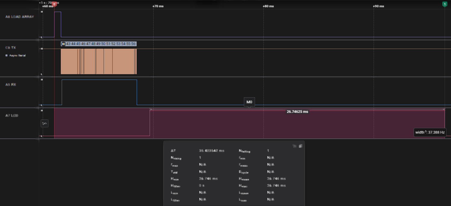
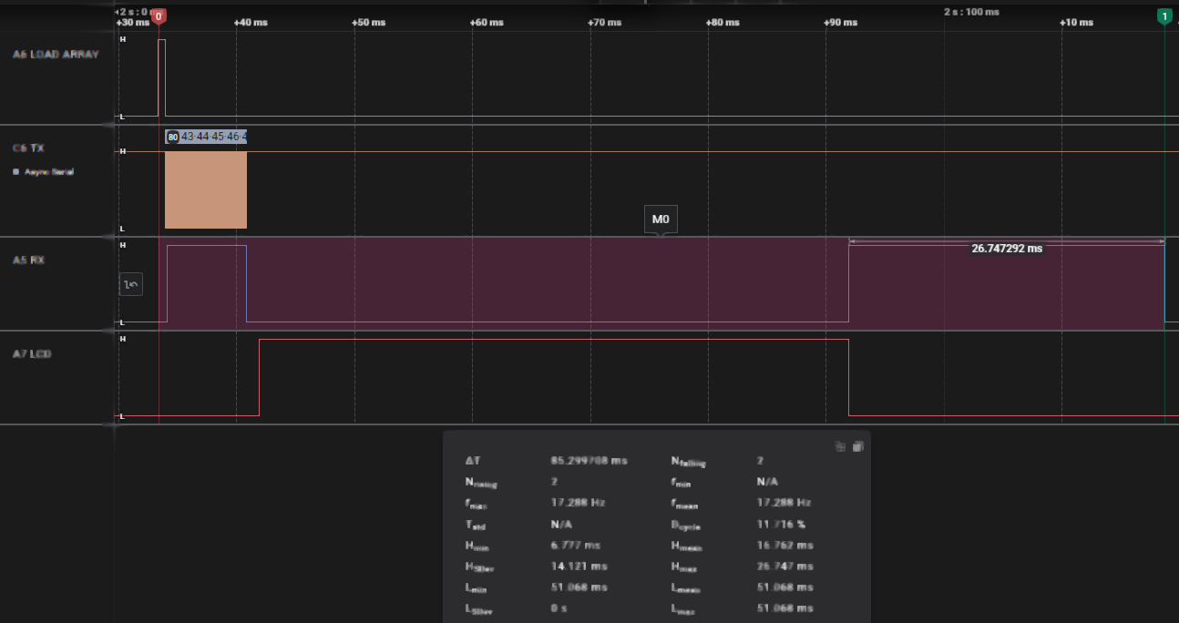
    Saleae probe timings from before Load Array in TX to after Lcdout in RX


    TX/RX using aliases, 35.4 mSec:

    Name:  Load alias v4.png
Views: 142
Size:  73.2 KB


    TX/RX using strcpy, now 85.2 mSec, adds 50.0 mSec step during strcpy:

    Name:  Load strcpy v4.png
Views: 110
Size:  76.4 KB


    LCD displayed properly "+" to "z":

    Name:  Load LCD.jpg
Views: 108
Size:  69.1 KB
    Last edited by Demon; - 20th March 2025 at 03:15.
    My Creality Ender 3 S1 Plus is a giant paperweight that can't even be used as a boat anchor, cause I'd be fined for polluting our waterways with electronic devices.

    Not as dumb as yesterday, but stupider than tomorrow!

Similar Threads

  1. Decoding serial data bytes and nibbles.
    By retepsnikrep in forum mel PIC BASIC Pro
    Replies: 6
    Last Post: - 18th January 2018, 08:22
  2. Bits, Bytes Words and Arrays
    By Melanie in forum FAQ - Frequently Asked Questions
    Replies: 24
    Last Post: - 14th June 2016, 07:55
  3. ORing / ANDing bytes or words
    By mmargolis in forum mel PIC BASIC Pro
    Replies: 1
    Last Post: - 19th March 2011, 20:12
  4. Success! Are they 'words' or are they 'bytes'?
    By BitHead in forum mel PIC BASIC Pro
    Replies: 3
    Last Post: - 27th December 2009, 16:54
  5. Codespace Saving Tip... Don't mix Words and Bytes
    By Melanie in forum Code Examples
    Replies: 0
    Last Post: - 18th June 2004, 10:23

Members who have read this thread : 14

You do not have permission to view the list of names.

Posting Permissions

  • You may not post new threads
  • You may not post replies
  • You may not post attachments
  • You may not edit your posts