SOLVED: How can I reduce ADC jitter


+ Reply to Thread
Results 1 to 40 of 96

Hybrid View

  1. #1
    Join Date
    Jan 2005
    Location
    Montreal, Quebec, Canada
    Posts
    3,170


    Did you find this post helpful? Yes | No

    Default Re: SOLVED: How can I reduce ADC drift

    Quote Originally Posted by richard View Post
    - did not touch VREFs,
    What do you mean by this , you have changes pos vref to fvr buffer1- used FVR 4x with 5 VDC in,
    which will turn out to be a mistake since pots use vdd as top input , by doing this you have lost 20% of their travel range...
    I meant, did not touch VREF-, sorry.

    If I use VREF+ = VDD, my ADC readings stop at 1000 or so.
    If I use VREF+ = FVRx4, my readings reach 1023.

    Weird.


    ...- used FOSC / 128,way too slow , while not out of acceptable range fosc/32 is more reasonable...


    I've switched to 32 as well.


    ...used average of 16 ADC readings,
    not sure about that , its not necessary either if every thing else is ok ...
    If I don't use averages, I jump all over like this:

    Code:
    OldADC1:00847  ADCin:00844  Diff:00003
    OldADC1:00844  ADCin:00847  Diff:00003
    OldADC1:00847  ADCin:00844  Diff:00003
    OldADC1:00844  ADCin:00848  Diff:00004
    OldADC1:00848  ADCin:00845  Diff:00003
    OldADC1:00845  ADCin:00848  Diff:00003
    OldADC1:00848  ADCin:00844  Diff:00004

    ...- used USART to show results
    - added PAUSEUS 1 after all ADC operations - THIS NEEDS TO BE VERIFIED IF IT'S NECESSARY, it was just to make sure things worked.
    it does nothing useful ...
    I removed them.


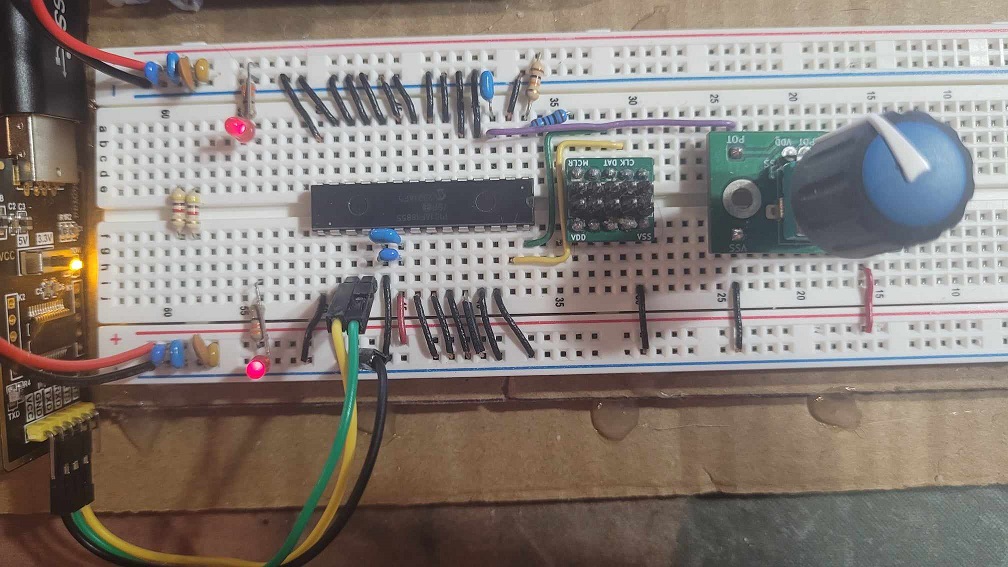
    ...my schema , added another supply rail straddling 10k pot , without series wiper resistor to an2
    not no none nil caps across an inputs

    typical raw readings
    Code:
    R 827    669
    R 826    669
    R 826    669
    R 826    668
    R 825    669
    R 827    669
    R 826    669
    R 826    669
    R 826    668
    R 825    668
    R 827    670
    R 826    669
    R 825    668
    R 827    669
    R 827    669
    Envious emote...


    ...
    DEFINE ADC_BITS 10 ' 10-bit Analog to digital
    DEFINE ADC_SAMPLEUS 5 ' Set sampling time in uS...
    Reduced mine from 50 down to 5 as well


    I just noticed that my temps on the 16F18855 goes over 100c when ADC runs; that's insane. I have no other routines running. If I stop ADC, it comes back down to 30ies.

    Name:  ADC high temps on 16F18855.jpeg
Views: 28921
Size:  142.9 KB


    I took everything non-essential off the breadboard (just kept my 2 power LEDs):

    Name:  ADC circuit.jpg
Views: 28833
Size:  215.0 KB


    Code:
    #CONFIG
        __config _CONFIG1, _FEXTOSC_OFF & _RSTOSC_HFINT32 & _CLKOUTEN_OFF & _CSWEN_OFF & _FCMEN_ON
        __config _CONFIG2, _MCLRE_ON & _PWRTE_OFF & _LPBOREN_OFF & _BOREN_ON & _BORV_LO & _ZCD_OFF & _PPS1WAY_OFF & _STVREN_ON & _DEBUG_OFF
        __config _CONFIG3, _WDTCPS_WDTCPS_11 & _WDTE_OFF & _WDTCWS_WDTCWS_7 & _WDTCCS_LFINTOSC
        __config _CONFIG4, _WRT_OFF & _SCANE_available & _LVP_OFF
        __config _CONFIG5, _CP_OFF & _CPD_OFF
    #ENDCONFIG
    
    DEFINE OSC 32
    
    DEFINE  ADC_BITS 10                 ' 10-bit Analog to digital
    DEFINE  ADC_SAMPLEUS 5              ' Set sampling time in uS
    
    DEFINE  HSER_RXREG PORTC
    DEFINE  HSER_RXBIT 7
    DEFINE  HSER_TXREG PORTC
    DEFINE  HSER_TXBIT 6
    
    DEFINE  HSER_RCSTA 90h              ' Enable serial port & continuous receive
    DEFINE  HSER_TXSTA 24h              ' Enable transmit, BRGH = 1
    Define  HSER_BAUD 115200
    DEFINE  HSER_CLROERR 1              ' Clear overflow automatically
    DEFINE  HSER_SPBRGH  0
    DEFINE  HSER_SPBRG  68
    
    ;--- Setup registers -----------------------------------------------------------
    
    BAUDCON.3 = 1                       ' Enable 16 bit baudrate generator
    
    FVRCON = %10000011                  ' FIXED VOLTAGE REFERENCE CONTROL REGISTER
    '   bit 7   FVREN: Fixed Voltage Reference Enable bit
    '               1 = Fixed Voltage Reference is enabled
    '   bit 1-0 ADFVR<1:0>: ADC FVR Buffer Gain Selection bit
    '               11 = ADC FVR Buffer Gain is 4x, (4.096V)(2)
    
    'ADCON0 = %10000100                  ' ADC CONTROL REGISTER 0
    '   bit 7   ADON: ADC Enable bit
    '               0 = ADC is disabled
    '               1 = ADC is enabled
    '   bit 2   ADFRM0: ADC results Format/alignment Selection
    '               1 = ADRES and ADPREV data are right-justified
    '               0 = ADRES and ADPREV data are left-justified, zero-filled
    
    ADCLK = %00001111                   ' ADC CLOCK SELECTION REGISTER
    '   bit 5-0 ADCCS<5:0>: ADC Conversion Clock Select bits
    '               001111 = FOSC/32
    
    ADREF = %00000011                   ' ADC REFERENCE SELECTION REGISTER
    '   bit 4 ADNREF: ADC Negative Voltage Reference Selection bit
    '               0 = VREF- is connected to AVSS
    '   bit 1-0 ADPREF: ADC Positive Voltage Reference Selection bits
    '               11 = VREF+ is connected to FVR_buffer 1
    '               00 = VREF+ is connected to VDD
    
    ANSELA = %00000010                      ' Pin A1 = ADC (B5K)
    ANSELB = %00000000
    ANSELC = %00000000
    
    TRISA = %00000010                       ' Pin A1 = ADC input 1
    TRISB = %00000000                       ' Pin B7 = ...not available, ICSPDAT
                                            ' Pin B6 = ...not available, ICSPCLK
    TRISC = %11000000                       ' Pin C7 = RX      *** Datasheet requirement, INPUT ***
                                            ' Pin C6 = TX      *** Datasheet requirement, INPUT ***
    
    ADCinput            var WORD
    ADCdiff             var WORD
    OldADC1             var WORD
    
        Pause 500                           ' Let PIC and LCD stabilize
        ADCinput = 0
        ADCdiff = 0
        OldADC1 = 9999
    
    Mainloop:
     
    rem                 ADC1, B5K pot
    
        adcin 1, ADCinput
        ADCinput = ADCinput >> 6                                ' tried left justified for fun
        
        if ADCinput < oldADC1 then                              ' Calculate change in ADC
            ADCdiff = oldadc1 - ADCinput
        else
            ADCdiff =  ADCinput - oldadc1
        endif
    
        IF  ADCdiff > 2 then                                    ' Check for Diff over 2
            hserout [   "OldADC1:",     DEC5 oldadc1, "  ", _
                        "ADCin:",       DEC5 ADCinput, "  ", _
                        "Diff:",        DEC5 ADCdiff, 10]                             
            while TXSTA.1 = 0               ' Check TRMT bit
            wend
            oldADC1 = ADCinput
        else
            if ADCinput <> oldadc1 then                         '   ADC value diff than previous
                if ADCinput = 0 then                            '     Reached end of rotation
                    hserout [   "OldADC1:",     DEC5 oldadc1, "  ", _
                                "ADCin:",       DEC5 ADCinput, "  ", _
                                "Diff:",        DEC5 ADCdiff, "  ", 10]                             
                    while TXSTA.1 = 0               ' Check TRMT bit
                    wend
                    oldADC1 = ADCinput
                else
                    if ADCinput = 1023 then                     '     Reached start of rotation
                        hserout [   "OldADC1:",     DEC5 oldadc1, "  ", _
                                    "ADCin:",       DEC5 ADCinput, "  ", _
                                    "Diff:",        DEC5 ADCdiff, 10]                             
                        while TXSTA.1 = 0               ' Check TRMT bit
                        wend
                        oldADC1 = ADCinput
                    endif
                endif
            endif
        endif
    
      GOTO Mainloop
    
    end
    I know I can join those Ifs to check for end of rotation, I just wanted to keep code simple to make sure everything was getting picked up.

    Averages was why sometimes it would not reach 0 or 1023.

    It works, but it has jumps of 3 now. Gonna see if more caps can reduce that.


    No clue why ADC is running so hot, specs say 85c is normal operating temp.


    The mounting holes are "slightly" warm, never noticed that before.

    Name:  Pot infrared.jpeg
Views: 22629
Size:  143.5 KB Name:  Pot normal.jpeg
Views: 22667
Size:  155.6 KB
    My Creality Ender 3 S1 Plus is a giant paperweight that can't even be used as a boat anchor, cause I'd be fined for polluting our waterways with electronic devices.

    Not as dumb as yesterday, but stupider than tomorrow!

  2. #2
    Join Date
    Jan 2005
    Location
    Montreal, Quebec, Canada
    Posts
    3,170


    Did you find this post helpful? Yes | No

    Default Re: SOLVED: How can I reduce ADC drift

    Quote Originally Posted by Demon View Post
    ...The mounting holes are "slightly" warm, never noticed that before.

    Attachment 9922 Attachment 9923
    I just checked the mounting holes on my test LCD, the holes do the same thing and the LCD hasn't been connected in days.

    Copper/bare metal is at a different temp than the rest so the scanner detects it.
    My Creality Ender 3 S1 Plus is a giant paperweight that can't even be used as a boat anchor, cause I'd be fined for polluting our waterways with electronic devices.

    Not as dumb as yesterday, but stupider than tomorrow!

  3. #3
    Join Date
    Jan 2005
    Location
    Montreal, Quebec, Canada
    Posts
    3,170


    Did you find this post helpful? Yes | No

    Default Re: SOLVED: How can I reduce ADC drift

    Either my PIC is damaged, or something is whacked inside the breadboard.

    105c and wasn't stopping.

    Code:
    #CONFIG
        __config _CONFIG1, _FEXTOSC_OFF & _RSTOSC_HFINT32 & _CLKOUTEN_OFF & _CSWEN_OFF & _FCMEN_ON
        __config _CONFIG2, _MCLRE_ON & _PWRTE_OFF & _LPBOREN_OFF & _BOREN_ON & _BORV_LO & _ZCD_OFF & _PPS1WAY_OFF & _STVREN_ON & _DEBUG_OFF
        __config _CONFIG3, _WDTCPS_WDTCPS_11 & _WDTE_OFF & _WDTCWS_WDTCWS_7 & _WDTCCS_LFINTOSC
        __config _CONFIG4, _WRT_OFF & _SCANE_available & _LVP_OFF
        __config _CONFIG5, _CP_OFF & _CPD_OFF
    #ENDCONFIG
    DEFINE OSC 4
    ANSELA = %00000010                      ' Pin A1 = ADC (B5K)
    ANSELB = %00000000
    ANSELC = %00000000
    TRISA = %00000010                       ' Pin A1 = ADC input 1
    TRISB = %00000000                       ' Pin B7 = ...not available, ICSPDAT
                                            ' Pin B6 = ...not available, ICSPCLK
    TRISC = %11000000                       ' Pin C7 = RX      *** Datasheet requirement, INPUT ***
                                            ' Pin C6 = TX      *** Datasheet requirement, INPUT ***
    ADCinput            var WORD
    
        Pause 500                           ' Let PIC and LCD stabilize
        ADCinput = 0
    
    Mainloop:
        adcinput = 1023
    end
    My Creality Ender 3 S1 Plus is a giant paperweight that can't even be used as a boat anchor, cause I'd be fined for polluting our waterways with electronic devices.

    Not as dumb as yesterday, but stupider than tomorrow!

  4. #4
    Join Date
    May 2013
    Location
    australia
    Posts
    2,645


    Did you find this post helpful? Yes | No

    Default Re: SOLVED: How can I reduce ADC drift

    i simply hate this , all these pins made into outputs , shorted to gnd , no attempt to set them low
    at power up are they low? before you short it all out
    worst idea ever for breadboarding , i leave all pins as inputs unless they need to be an output
    all this care re floating inputs is complete bull shit. for a battery operated device it will save a few microwatts that's it.
    for the finished manufactured product sure do it , for bread boarding its dangerous nonsense where every mistake will be a bad one


    Code:
    TRISA = %00000010                       ' Pin A1 = ADC input 1
    TRISB = %00000000                       ' Pin B7 = ...not available, ICSPDAT
                                            ' Pin B6 = ...not available, ICSPCLK
    TRISC = %11000000


    I took everything non-essential off the breadboard (just kept my 2 power LEDs):
    and all the dangerous grounds
    Warning I'm not a teacher

  5. #5
    Join Date
    Jan 2005
    Location
    Montreal, Quebec, Canada
    Posts
    3,170


    Did you find this post helpful? Yes | No

    Default Re: SOLVED: How can I reduce ADC drift

    I realized something was seriously wrong when that nothing circuit was taking 670mA. I added:

    Code:
    PORTA = %00000000
    PORTB = %00000000
    PORTC = %00000000
    Before the ANSELx and TRISx and it's taking 20mA now, 33c with no ADC, just ADCinput set at 1023 and the HSEROUT loop.
    My Creality Ender 3 S1 Plus is a giant paperweight that can't even be used as a boat anchor, cause I'd be fined for polluting our waterways with electronic devices.

    Not as dumb as yesterday, but stupider than tomorrow!

  6. #6
    Join Date
    Jan 2005
    Location
    Montreal, Quebec, Canada
    Posts
    3,170


    Did you find this post helpful? Yes | No

    Default Re: SOLVED: How can I reduce ADC drift

    Quote Originally Posted by richard View Post
    ... i leave all pins as inputs unless they need to be an output
    all this care re floating inputs is complete bull shit....
    I try to keep my development code as close to final as possible, cause I know I'll forget to change stuff back. At least this way I can fire and forget the pin initialization.

    But yeah, major bonehead move on my part. I put the old PIC back in and it runs at 20mA too. Gonna leave that 1st PIC in, just in case I do some other numbnut thing.

    Thanks mucho Richard.


    EDIT: Now this warning will follow my code for the rest of the development.

    Code:
    PORTA = %00000000                       '-------------------------------------------' 
    PORTB = %00000000                       '       ALWAYS SET PINS LOW FIRST           '
    PORTC = %00000000                       '-------------------------------------------' 
    Last edited by Demon; - 4th March 2025 at 04:26.
    My Creality Ender 3 S1 Plus is a giant paperweight that can't even be used as a boat anchor, cause I'd be fined for polluting our waterways with electronic devices.

    Not as dumb as yesterday, but stupider than tomorrow!

Similar Threads

  1. SOLVED - IOC works on B0 but not B5
    By Demon in forum General
    Replies: 19
    Last Post: - 26th September 2024, 21:11
  2. Replies: 6
    Last Post: - 5th November 2023, 16:26
  3. trying to reduce current consumption on a 12HV615
    By Max Power in forum mel PIC BASIC Pro
    Replies: 8
    Last Post: - 30th November 2011, 14:57
  4. Unwanted output signal jitter
    By LinkMTech in forum mel PIC BASIC Pro
    Replies: 20
    Last Post: - 18th January 2008, 02:31
  5. Dmx Solved !!!!!!!
    By oscar in forum mel PIC BASIC Pro
    Replies: 18
    Last Post: - 2nd July 2005, 21:57

Members who have read this thread : 17

You do not have permission to view the list of names.

Posting Permissions

  • You may not post new threads
  • You may not post replies
  • You may not post attachments
  • You may not edit your posts