

kinda makes me wonder how that can even workTried shifting out low 4 bits.
...mostly stable
But now the high range only goes up to 976 or so.
perhaps show your code


kinda makes me wonder how that can even workTried shifting out low 4 bits.
...mostly stable
But now the high range only goes up to 976 or so.
perhaps show your code
Warning I'm not a teacher

I have to clean it up first. It's a mess from all the trials.
My Creality Ender 3 S1 Plus is a giant paperweight that can't even be used as a boat anchor, cause I'd be fined for polluting our waterways with electronic devices.
Not as dumb as yesterday, but stupider than tomorrow!

You had slide pots made for you? That can't be cheap...
With those values it probably does not matter but don't just write it off.It's a linear 10K slide, my rotaries are 5K, but that shouldn't matter.
The sample & hold circuit in the ADC works by temporarily connecting a small capacitor to the selected input. This capacitor is charged thru the impedance of the voltage source (your potentiometer) - which varies depending on where along the "track" the slider is positioned. If the jitter is worse with the slider closer to the bottom than to the top it could be an issue.
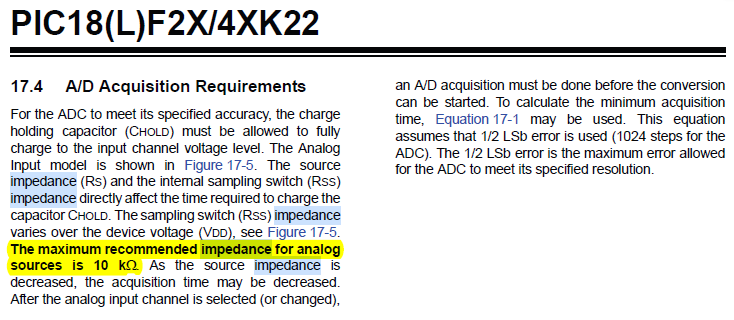
Look at section 17.4 (or table 27.21) of the datasheet for the 26K22. It states that the maximum recommended impedance is 3k.
If nothing else you could try filtering the wiper voltage with a capacitor, say 1uF and then buffer the signal with a rail-to-rail OP before feeding it to the PIC.

With these pots (slider 10K) I would first use an opamp as buffer, feed a 1K series resistor, then a parallel 10uF cap and then a buffer opamp again before driving PIC input.
Just to be sure...
Most PIC I used before had 10K input impedance of Sample and Hold ciruit. This 3K that Henrik mentioned is too low for a 10K pot!
Ioannis
I had never seen that suggested in my "debounce potentiometer" research. Starting to look into it (after I understand what it's doingOriginally Posted by Ioannis

).
First time I hear that too.
My Creality Ender 3 S1 Plus is a giant paperweight that can't even be used as a boat anchor, cause I'd be fined for polluting our waterways with electronic devices.
Not as dumb as yesterday, but stupider than tomorrow!
(made for me) as in I ordered them on Alibaba, but they were stock, no customizations. They only mods I had done, were within the company's available options (single slide, longer handle, dust cover, etc).
I just checked, it's similar at both ends (visibly 3-4 bits jittering on my LCD display)
Oh snap, I've been seeing everywhere that 10K is the accepted norm for ADC on Microchip PICs. Never even checked the specific datasheet (that and my mind is having a hard time using the word impedance and associating it with resistance - don't ask me why).
Starting to google that now...
My Creality Ender 3 S1 Plus is a giant paperweight that can't even be used as a boat anchor, cause I'd be fined for polluting our waterways with electronic devices.
Not as dumb as yesterday, but stupider than tomorrow!
Henrik, is it possible your datasheet has an error?
Is it possible you were looking at a low-voltage variant?
Mine says 10K max. I had actually highlighted it during my research on ADC.
(turns out Mr E really did teach me to RTFM
My Creality Ender 3 S1 Plus is a giant paperweight that can't even be used as a boat anchor, cause I'd be fined for polluting our waterways with electronic devices.
Not as dumb as yesterday, but stupider than tomorrow!
The higher the source (pot) resistance the greater the error in the voltage that PIC ADC will read. So, adding an opamp as a buffer will add no load to the source (pot) as it ihas very large input resistance (impedance that is) and too low, in the order of ohms output resistance. So it will drive any ADC input with no error introduced. For your experiments I proposed two opamps to buffer the r-c filter, as this filter will increase source resistance.
Ioannis
I'm looking at this post:
https://electronics.stackexchange.co...c-analog-input
I have 3 slide pots, so I found a quad op-amp OPA4314 at JLCPCB:
https://wmsc.lcsc.com/wmsc/upload/fi...WR_C129333.pdf
Interesting stuff. This never came up in my research to debounce a pot. They quickly lose me when they talk about frequencies and Nyquist. I'm assuming this relates with audio. I'm just sampling a pot and wouldn't know how to tweak that R/C combo.
The R/C combo here is WAAAAY lower:
https://electronics.stackexchange.co...t-input-to-adc
Found an explanation on how to chose the R/C combo between a buffer and ADC here:
https://electronics.stackexchange.co...-an-adc-input:
It points to a TI note that suggests 100R/1nF for the OPAx365 (in the image). I'm assuming this is an excellent starting point; TI describes it as "ideal for driving sampling analog-to-digital converters (ADCs)".
https://wmsc.lcsc.com/wmsc/upload/fi...BVR_C96626.pdf
Only available in single and dual, but still relatively cheap (from what I expected, I'm just happy it's available at JLCPCB).
Last edited by Demon; - 8th August 2024 at 02:38.
My Creality Ender 3 S1 Plus is a giant paperweight that can't even be used as a boat anchor, cause I'd be fined for polluting our waterways with electronic devices.
Not as dumb as yesterday, but stupider than tomorrow!
a voltage follower amp is really only a benefit if the signal source impedance is so high that the adc input loads the signal so much to make it inaccurate. it will not smooth out a crappy pot if anything it may accentuate it.
a lowpass filter will help whether its analog pre adc or digital post adc will make little difference
right now I'm working with FSR'S [force sensitive resistors] with 200k to 500k resistances on a pic 16f18426
no problem what so ever
what do the pots perform like when measured on a ohmmeter [an analog one would be ideal]
if they are really that bad then the resolution achievable will be low no matter how you go about it
especially if there are dead spots
Last edited by richard; - 8th August 2024 at 04:09.
Warning I'm not a teacher
Maybe because you do not debounce a pot but only a switch or push button. Pots are filtered in the rare case of noise. Usually are rock stable and with a couple of averaging there is no problem.
Ioannis
HENRIK FOR THE WIN!
I migrated to a 16F1937 and the pot is now acting marvelously. I now jitters at most only 1 value (what I initially expected when the wiper straddles zones).
WOOT!!!
My Creality Ender 3 S1 Plus is a giant paperweight that can't even be used as a boat anchor, cause I'd be fined for polluting our waterways with electronic devices.
Not as dumb as yesterday, but stupider than tomorrow!
I do not think this made the difference...! Probably a bad connection.
The lower sample and hold impedance would add error to your A-to-D conversion. Not jitter.
Ioannis
+1I do not think this made the difference...! Probably a bad connection.
me too or bad code
Warning I'm not a teacher
I just noticed this gem from Darrel:
https://dt.picbasic.co.uk/CODEX/AtoDAveraging
You know how the least sigificant digit will "wobble" back and forth between 2 numbers? It's half-way between 2 numbers and it can't quite figure out which one it should be. Well, this adds hysteresis to the averaging routine to eliminate that.
My Creality Ender 3 S1 Plus is a giant paperweight that can't even be used as a boat anchor, cause I'd be fined for polluting our waterways with electronic devices.
Not as dumb as yesterday, but stupider than tomorrow!
 Members who have read this thread : 14
You do not have permission to view the list of names.
 Posting Permissions
 Reply With Quote
Bookmarks