you cannot, the smallest element is 1 byte ie one column[page] of 8 rows
you cannot, the smallest element is 1 byte ie one column[page] of 8 rows
Warning I'm not a teacher
Right, so you are talking about using data in a more efficient way using the vertical display mode as described in figure 10-4, correct?you cannot
![Name: 2023-12-03 19_48_22-SSD1306 COMMAND reference.pdf - [SSD1780] - SumatraPDF.png
Views: 5239
Size: 153.0 KB](https://www.picbasic.co.uk/forum/attachment.php?attachmentid=9500&d=1701629442)
Roger
yes , aligning the font data packing with the ssd1306's memory page layout is more efficient usage of the 14 bit width of the flash memory
while it will still need some clever manipulation to unpack it into a 8 bit data stream

Warning I'm not a teacher
Here is a simple code to get started with this 72x40 display.
I also include the SSD1306 command and display's datasheets.
Since I use EXCEL to design characters, here's the sheet you may want to have a look at.
And again, lots of thanks to Richard

Roger
You seem to have the communication to the controller well under control
next step is to try to store a font economically, you have probably discovered a large font on a very resource limited chip
like a 690 stored as a series of code structures like
I2CWrite SDA,SCL,I2CDevice,_
[$40,192,224,240,248,252,126,63,63,63,63,63,63,63,6 3,126,252,248,240,224,192,_
255,255,255,255,128,128,128,128,128,128,128,128,12 8,128,128,128,255,255,255,255,_
255,255,255,255,15,15,15,15,15,15,15,15,15,15,15,1 5,255,255,255,255,_
255,255,255,255,0,0,0,0,0,0,0,0,0,0,0,0,255,255,25 5,255]
will by the time you have 10 digits covered will have blown 75% of the chips flash.
fonts can be stored in much better ways, even expanded out as the are read back
Warning I'm not a teacher
Richard, can you point me the direction to do this?fonts can be stored in much better ways
Should I use some kind of algorithm where repetitive numbers could be stored differently or find a way to make better use of the 14 bits word size of the 16F690?
Roger
the font is just a simple block of data
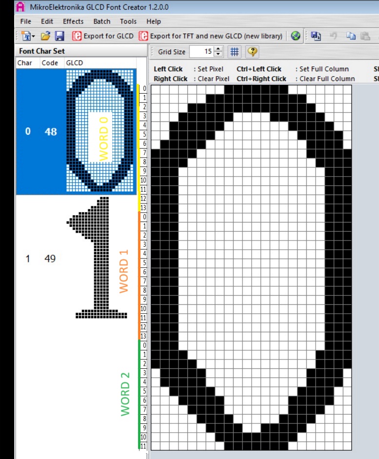
this one is for digits 0 to 9 + "." + "%" its 14 bits high and 10 bits wide [to match chip flash]
so total size is 120 words
for convenience lets locate it a the end of flash - 120 words ie. 0xf88
note this is only partially "filled" in and not very carefully at that
normally i would make the font an include and give it a label rather than manually locate it like thisCode:asm ;incomplete and very rough font 14x10 org 0xf88 dw 0x1ffc,0x3ffe,0x3006,0x3006,0x3006,0x3006,0x3006,0x3006,0x3ffe,0x1ffc ;"0" dw 0,0x300C,0x300E,0x300F,0x3ffF,0x3ffF,0x3ffF,0x3000,0x3000,0 dw 0x3806,0x3C07,0x3E03,0x3703,0x3383,0x31E3,0x30F3,0x307F,0x303E,0 dw 0x3018,0x3006,0x3186,0x3186,0x3186,0x3186,0x3186,0x3006,0x3cf8,0x1ffc ;"3" dw 0,0x3ffe,0,0x3ffe,0,0x3ffe,0,0x3ffe,0,0 dw 0,0x3ffe,0,0x3ffe,0x3ffe,0x3ffe,0,0x3ffe,0,0 dw 0x3ffe,0x3ffe,0x3ffe,0,0,0,0,0x3ffe,0x3ffe,0x3ffe dw 0x3ffe,0x3ffe,0x3ffe,0,0,0x3ffe,0,0x3ffe,0x3ffe,0x3ffe dw 0x1ffc,0x3ffe,0x3186,0x3186,0x3186,0x3186,0x3186,0x3186,0x3ffe,0x1ffc ;"8" dw 0,0x3ffe,0x3ffe,0x3ffe,0x3ffe,0x3ffe,0x3ffe,0x3ffe,0x3ffe,0x3ffe dw 0,0,0,0xE00,0x1F00,0x1F00,0xE00,0,0,0 ;"." dw 0x181f,0xC11,0x611,0x31f,0x1C0,0x60,0x1F38,0x110c,0x1106,0x1F02 ;"%" endasm
dt's macro as found in dt-ints is ideal to find and numerate the font address
when the fonts address is known its simple to use readcode command to retrieve font dataGetAddress macro Label, Wout
CHK?RP Wout
movlw low Label ; get low byte
movwf Wout
movlw High Label ; get high byte
movwf Wout + 1
endm
Last edited by lester; - 8th December 2023 at 09:44. Reason: Changed Thread Title
Warning I'm not a teacher
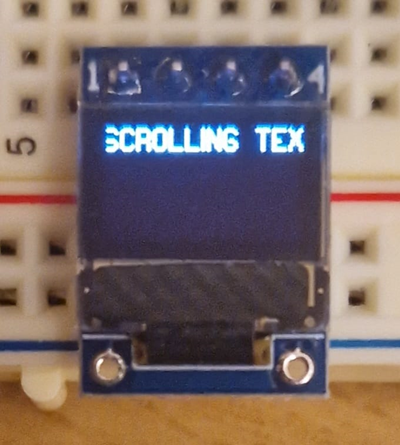
Just for fun, scrolling text example

Roger
i'm not seeing a font , i had a look at a 40x18 font this morning with my new 72x40 that just arrived
encoded this way seems the best compromise for easy of unpacking into a 18 x 5 byte stream to send to display
i dont like most of you inital sfr settings
i would replace the entire section with
OSCCON = $70 ;% 01110000 'Internal RC set to 8MHZ
for these reasons
OPTION_REG = % 10000000 'PORT A&B Pull-Ups disabled (see WPUA & WPUB)
Pull-Ups are set that way by default anyway . that does other things to that may later prove to be incorrect Like set int edge to falling, reassign and alter the prescaler, change timer 0 clock source
OSCCON = % 11100000 'Internal RC set to 8MHZ
no 'OSCCON = % 01110000 for 8mhz you have set it for 4 mhz
ANSEL = % 00010100 'Select analog inputs Channels 0 to 7 (AN2 + AN4 selected)
ok but you then go on to make those pins be digital outputs , not recommended except for smoke generation if used as analog inputs
ADCON0 = % 10000000 'A/D Module (Bit5:2 select channels 0:11)
ADCON1 = % 00000000 'A/D control register
why ? makes no sense adc is off by default
CM1CON0 = % 00000000 'Comparator1 Module is OFF
CM2CON0 = % 00000000 'Comparator2 Module is OFF
why ? Comparator 1 and 2 Modules are OFF by default
INTCON = % 00000000 'INTerrupts CONtrol (TMR0 OFF)
why serves no purpose ints are off by default
TRISA = % 00000000 'Set Input/Output (0 to 5)
bad call when an2
TRISB = % 00000000 'Set Input/Output (4 to 7)
bad call when 4,6 used for i2c
TRISC = % 00000000 'Set Input/Output (0 to 7)
bad call when an4
why ? i2c pins can left as be inputs
when breadboarding leave unused pins as inputs. fine set them as low outputs for the "production" version if a few microwatts of power dissipation makes a difference
PORTB = % 00000000 'Ports High/Low (4 to 7)
why ? i2c pins being set low is not useful
Warning I'm not a teacher
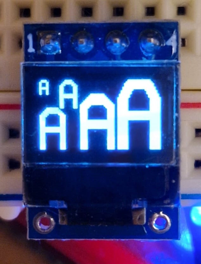
i have tried a 14x10 , a 14x10 doubled to 28x20
a 13x7 doubled to 26x14 and tripled to 39x21
they all work ok. imho by leaps and bounds a 40x18 full size font looks best and is only 540 words for ten digits
Last edited by richard; - 9th December 2023 at 08:12.
Warning I'm not a teacher
Richard,
You're absolutely right about the useless register settings I mention in my code.
Most of them, if not all, just reflect their default state as per datasheet.
This is because I use a pic specific template so they are there everytime I start a new project and ready to be deleted in case of no use
BTW, your video looks great!!
Roger
Yes, I agree, this is definitively the hardest part to get it work.
Richard, how did you come to this $68 value please? I can't figure it out
'======= SSD1306 I2C OLED initialization ================================================== =========
COM = $AE : GOSUB SEND_COMMAND ' turn off OLED panel
COM = $D5 : GOSUB SEND_COMMAND ' set display clock divide ratio/oscillator frequency
COM = $F0 : GOSUB SEND_COMMAND ' set divide ratio
COM = $A8 : GOSUB SEND_COMMAND ' set multiplex ratio
COM = $27 : GOSUB SEND_COMMAND ' 1/40 duty
COM = $D3 : GOSUB SEND_COMMAND ' set display offset
COM = $00 : GOSUB SEND_COMMAND
COM = $40 : GOSUB SEND_COMMAND ' set display start line
COM = $8D : GOSUB SEND_COMMAND ' set Charge Pump enable/disable
COM = $14 : GOSUB SEND_COMMAND ' set(0x10) disable
COM = $20 : GOSUB SEND_COMMAND ' Addressing Setting Command Table
COM = $00 : GOSUB SEND_COMMAND ' Page Addressing Mode
COM = $A1 : GOSUB SEND_COMMAND ' set segment re-map: column address 127 is mapped to SEG0
COM = $C8 : GOSUB SEND_COMMAND ' Set COM Output Scan Direction 64 to 0
COM = $DA : GOSUB SEND_COMMAND ' set com pins hardware configuration
COM = $12 : GOSUB SEND_COMMAND ' Sequential COM pin configuration
COM = $AD : GOSUB SEND_COMMAND ' Internal IREF Setting
COM = $30 : GOSUB SEND_COMMAND ' --
COM = $81 : GOSUB SEND_COMMAND ' set contrast control register
COM = $2F : GOSUB SEND_COMMAND ' set contrast value 0..255
COM = $D9 : GOSUB SEND_COMMAND ' set pre-charge period
COM = $22 : GOSUB SEND_COMMAND ' set pre-charge value
COM = $DB : GOSUB SEND_COMMAND ' set vcomh deselect level
COM = $20 : GOSUB SEND_COMMAND ' set vcomh value
COM = $A4 : GOSUB SEND_COMMAND ' Disable Entire Display On
COM = $A6 : GOSUB SEND_COMMAND ' set normal display
COM = $0C : GOSUB SEND_COMMAND ' set lower column address
COM = $11 : GOSUB SEND_COMMAND ' set higher column address
COM = $68 : GOSUB SEND_COMMAND ' set display start line register
COM = $AF : GOSUB SEND_COMMAND ' turn on OLED panel
Last edited by flotulopex; - 12th December 2023 at 18:02.
Roger
the info supplied with the display makes calculating the value somewhat difficult . in fact i cannot see the connection at allRichard, how did you come to this $68 value please? I can't figure it out
the command basically sets where the memory line representing page 0 bit 0 maps to the physical display top row pixels, it can be vertically offset by 0 to 63 pixels in a virtually identical way to the way the display scrolls horizontally
it needed to be offset by -23 pixels to get the top row to align with page 0 bit 0
command range = 0x40 to 0x7f , 0x7f - 23 = 0x68
Last edited by richard; - 12th December 2023 at 22:23.
Warning I'm not a teacher
Well, I think I'm just gonna remember this settings "as is".
Thanks for trying to make things more clear for me
Roger
This is very interesting thread, giving me some hope that I will be able to use OLED screens with PBP one day, but I have a quesiton - 24C64 or something like that costs under $1. Why not use it for font storage?
I have a quesiton - 24C64 or something like that costs under $1. Why not use it for font storage
because you can save your $1 and another one by buying a better pic to start with and :-
not have a costlier more complex circuit board .
use a standard font file generated by glcd font creator.
its faster, uses hardware i2c and can do proper graphics too.
as i said at the beginning if you want easy get a pic 18

Last edited by richard; - 16th December 2023 at 05:58.
Warning I'm not a teacher
So expensive
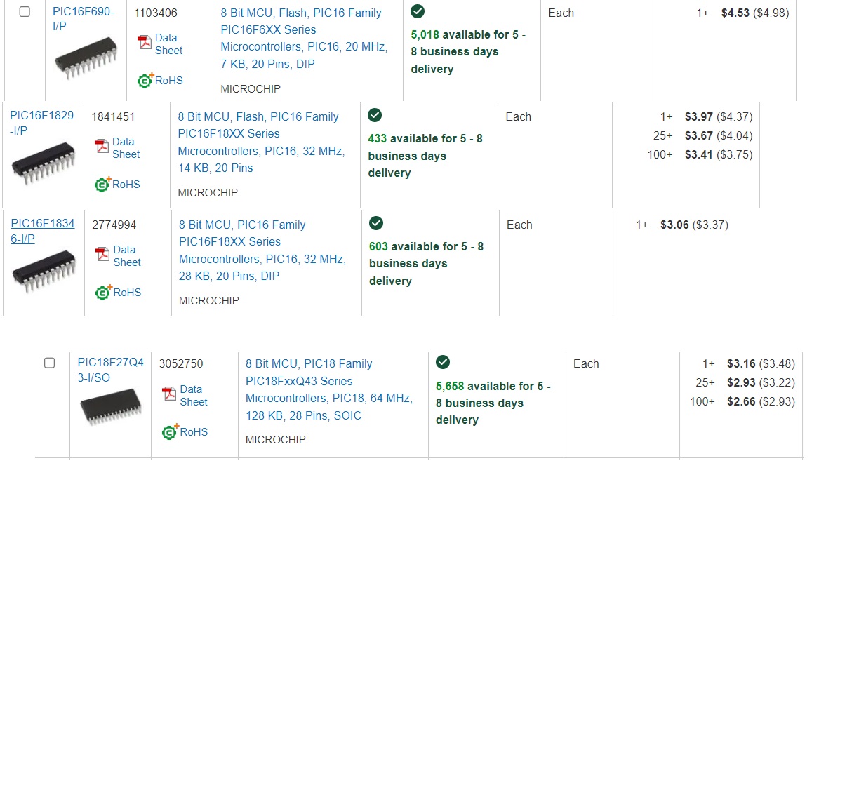
I'm buying 2nd hand 886 and 1829 for about 50 and 90 cents in China
Since I'm not doing anything commercial, this is just fine for me.
And by the way, I don't see any reasons, why you can't write GLCD (which can't save file on windows 10-11) generated or any other software generated font into external EEPROM.
Nor do I , but I have never come anything to make a bin or hex file easily from the generated codedon't see any reasons, why you can't write GLCD generated or any other software generated font into external EEPROM.
mine works perfectly win 10 and 11 , make sure to add the .lcd extension to the file name when saving it otherwise it goes funny(which can't save file on windows 10-11)
Warning I'm not a teacher
Because this thread will be followed with "how can I speed up my OLED display routines?".Why not use it for font storage?
The choice is obviously yours, but the 18F27Q43 has 128K of flash, 8K of ram, and runs at 64MHz.
The only downside is the hardware I2C peripheral isn't compatible with the old MSSP I2C, so you're stuck using PBP's software I2CWRITE/I2CREAD or rolling your own (which is not trivial for these new parts).
Hi Richard, & all others in the post.
I've just started out with my OLED display, writing in PIC assembler so I'm presently reading the fine-print on the SSD1306 datasheet to ensure I leave no bits un-turned. I'm cross-referencing my program to others I've found, albeit none in assembler, as such I joined the forum to maybe smooth any glitches I stumble across as this discussion seems rather detailed.
Although the datasheet shows an approximate Initialise flowchart, I've noticed a few differences (in order) between some of the subroutines I've found:
An interesting one within the datasheet informs the Set-Charge-Pump command (8Dh) should be followed by the Display On (AFh) command, has yours been okay as such in your Richard?
Your 'set lower column address' & 'set higher column address', should these variables not be preceded with the actual 'Set Column Address' command, 21h?
Also, the 'Internal IREF Setting' command ($AD) , where in the datasheet is that command listed, I can find ample references to the Iref current & the calcs etc but can'f find the actual command.
If your sequence has proved okay, I'll use its order as a reference to set mine up, although I'll set Segment-0 as column-0 just to get it up & running then make changes as required.
Albeit writes to my CGRAM showed a blank display, as such I've yet to find if it's either my I2C timing (I'm bit banging), (OR) my actual programming sequence, hence firstly confirming the Initialise sequence.
This is my sequence;
0AEh ; Set Display OFF. AE h = display OFF, while AF= display ON.
0D5h ; Set Display Clock Divide Ratio/ Oscillator Frequency.
80h ; (value)
0A8h ; Set Multiplex Ratio.
3Fh ; (value)
40h ; Set Display Start Line (row) 0 - 63 (40h 7Fh). [as I'm using the 64x32 display]
20h ; Set Memory Addressing Mode;
00h ; Three choices, I use the Horizontal mode.
21h ; Set Column Address;
00h ; Column start address (0 for me)
3Fh ; Column end address (63 for me) [as I'm using the 64x32 display]
22h ; Set Page Address;
00h ; PAGE start address (0 for me).
03h ; PAGE end address (3 for me). [as I'm using the 64x32 display]
81h ; Set Contrast Control.
0CFh ; (value)
0D9h ; Set Pre-charge period.
0F1h ; (value)
0DBh ; Set VCOMH Deselect Level.
40h ; (value)
0A4h ; Entire display on. A4h= Display as per RAM content. A5h= Display is ON, **BUT** unafected by changes to RAM content.
0A6h ; Set Normal/Inverse Display. A6h= normal, A7h= inverse.
0x8D ; Set charge pump;
0x14 ; (value) - ON
0AFh ; Turn Display ON.
Mark.
------------
'======= SSD1306 I2C OLED initialization ================================================== =========
COM = $AE : GOSUB SEND_COMMAND ' turn off OLED panel
COM = $D5 : GOSUB SEND_COMMAND ' set display clock divide ratio/oscillator frequency
COM = $F0 : GOSUB SEND_COMMAND ' set divide ratio
COM = $A8 : GOSUB SEND_COMMAND ' set multiplex ratio
COM = $27 : GOSUB SEND_COMMAND ' 1/40 duty
COM = $D3 : GOSUB SEND_COMMAND ' set display offset
COM = $00 : GOSUB SEND_COMMAND
COM = $40 : GOSUB SEND_COMMAND ' set display start line
COM = $8D : GOSUB SEND_COMMAND ' set Charge Pump enable/disable
COM = $14 : GOSUB SEND_COMMAND ' set(0x10) disable
COM = $20 : GOSUB SEND_COMMAND ' Addressing Setting Command Table
COM = $00 : GOSUB SEND_COMMAND ' Page Addressing Mode
COM = $A1 : GOSUB SEND_COMMAND ' set segment re-map: column address 127 is mapped to SEG0
COM = $C8 : GOSUB SEND_COMMAND ' Set COM Output Scan Direction 64 to 0
COM = $DA : GOSUB SEND_COMMAND ' set com pins hardware configuration
COM = $12 : GOSUB SEND_COMMAND ' Sequential COM pin configuration
COM = $AD : GOSUB SEND_COMMAND ' Internal IREF Setting
COM = $30 : GOSUB SEND_COMMAND ' --
COM = $81 : GOSUB SEND_COMMAND ' set contrast control register
COM = $2F : GOSUB SEND_COMMAND ' set contrast value 0..255
COM = $D9 : GOSUB SEND_COMMAND ' set pre-charge period
COM = $22 : GOSUB SEND_COMMAND ' set pre-charge value
COM = $DB : GOSUB SEND_COMMAND ' set vcomh deselect level
COM = $20 : GOSUB SEND_COMMAND ' set vcomh value
COM = $A4 : GOSUB SEND_COMMAND ' Disable Entire Display On
COM = $A6 : GOSUB SEND_COMMAND ' set normal display
COM = $0C : GOSUB SEND_COMMAND ' set lower column address
COM = $11 : GOSUB SEND_COMMAND ' set higher column address
COM = $68 : GOSUB SEND_COMMAND ' set display start line register
COM = $AF : GOSUB SEND_COMMAND ' turn on OLED panel
no , that is setting the offset of the actual display as it is overlaid into the memory mapYour 'set lower column address' & 'set higher column address', should these variables not be preceded with the actual 'Set Column Address' command, 21h?
its probably not a command at all but a data value that followed the contrast command that's become dislodged in space and time.Also, the 'Internal IREF Setting' command ($AD) , where in the datasheet is that command listed, I can find ample references to the Iref current & the calcs etc but can'f find the actual command.
Warning I'm not a teacher
I've just realised I'd wrote your name Richard, instead of Rogers, as it was his initialisation listing I was querying, no worry.
I see one of Roger's later posts shows the two subsequent bytes, as with the subsequent Page Address command ($22) two bytes.
The Internal IREF Setting' command ($AD), appears to be listed on older pdf's for the 72x40 type(?), a command not required on later board as set by a resistor.
I've sorted my glitch out, copying a double-byte send I2C section to create the triple byte I'd overlooked the unwanted I2C_Stop call before sending the 3rd byte, so was never seeing it.
Code:;====== call I2C_Start call I2C_Address movlw 00h ; 00=Command stream. movwf I2C_Command_or_Data call I2C_byte movlw 21h ;Column Address; movwf I2C_Command_or_Data call I2C_byte movlw 00h ; Low column. movwf I2C_Command_or_Data call I2C_byte movlw 3Fh ; High column. movwf I2C_Command_or_Data call I2C_byte call I2C_Stop ; ;====== call I2C_Start call I2C_Address movlw 00h ; 00=Command stream. movwf I2C_Command_or_Data call I2C_byte movlw 22h ;[3] Page Address; movwf I2C_Command_or_Data call I2C_byte movlw 00h ; Start page. movwf I2C_Command_or_Data call I2C_byte movlw 03h ; End page. movwf I2C_Command_or_Data call I2C_byte call I2C_Stop ; I2C_Start ;-- Start -- bcf PORTA,SDA ;START commence, call _nops bcf PORTA,SCK ; START complete. return I2C_Address ;-- Address_byte -- ;= 78h (bit [0] = R/W. Writing, so = 0. bcf PORTA,SDA ;bit 7 call clk_it bsf PORTA,SDA ;bit 6 call clk_it bsf PORTA,SDA ;bit 5 call clk_it bsf PORTA,SDA ;bit 4 call clk_it bsf PORTA,SDA ;bit 3 call clk_it bcf PORTA,SDA ;bit 2 call clk_it bcf PORTA,SDA ;bit 1 call clk_it bcf PORTA,SDA ;bit 0 (R/W bit) call clk_it ; return ; I2C_Ack ;-- Ack -- bsf STATUS,RP0 ;Page 1. bsf TRISA,SDA ;Set as input to release the line bcf STATUS,RP0 ;Page 0. call clk_it bsf STATUS,RP0 ;Page 1. bcf TRISA,SDA ;Set back to output. bcf STATUS,RP0 ;Page 0. return ; I2C_byte ;-- Command or Data byte -- movlw 08h movwf countbits ;count the 8 bits RLF byte_bits btfss I2C_Command_or_Data,7 goto low_bit1 bsf PORTA,SDA goto _clk1 low_bit1 bcf PORTA,SDA _clk1 call clk_it decfsz countbits,same goto _rlf goto I2C_Ack ;return _rlf rlf I2C_Command_or_Data goto byte_bits ; I2C_Stop ;-- Stop -- bcf PORTA,SDA ;Before STOP, ensure its low. call _nops bsf PORTA,SCK ;STOP commence, call _nops bsf PORTA,SDA ; STOP completed. ; call _nops call d50mS return ;I2C over.
Bookmarks