

apologies so it does16F887 has two PWM modules


apologies so it does16F887 has two PWM modules
Warning I'm not a teacher

Well, the different build has no such issue, but while using same code, it also uses different pinout (ADC input is PORTE.2 instead of PORTA.0), so in next days I will try to check existing build for issues.
It is very interesting, as I unpacked the original board and put it on the table, it no longer had that issue.
And after I packed the new board into small enclosure, it started to have exactly the same issue!
I added some checks to code and here is what I've found.
I'm using ADC to get the input from the keys.
ADC IN is tied to VDD via +10K resistor, and there are two buttons, one pulls that IN to GND, another also pulls to GND, but via another 10K resistor.
So when no button is pressed, ADC input reads 255. When 1st button is pressed - it is 0, and when 2nd button is pressed, it is about 127. (My code checks it to be above 100 and below 140)
So, what happens? When I have PWM with duty cycle less than 170 (assuming HPWM 1,170,2000), the ADC input sporadically starts to read as 127, instead of 255! The lower PWM duty cycle is, often that happens.
But this only happens when there are some wires connected to ADC input (even short ones, about 10cm). So I guess, this is an hardware issue, and adding 0.1uf capacitor to ADC IN should help?

Obviously this is an EMI problem. Somewhere your circuits acts like a transmitter (PWM sharp signals are what it needs to do so).
Maybe a wrong trace, maybe a cable that is in different place, who knows?
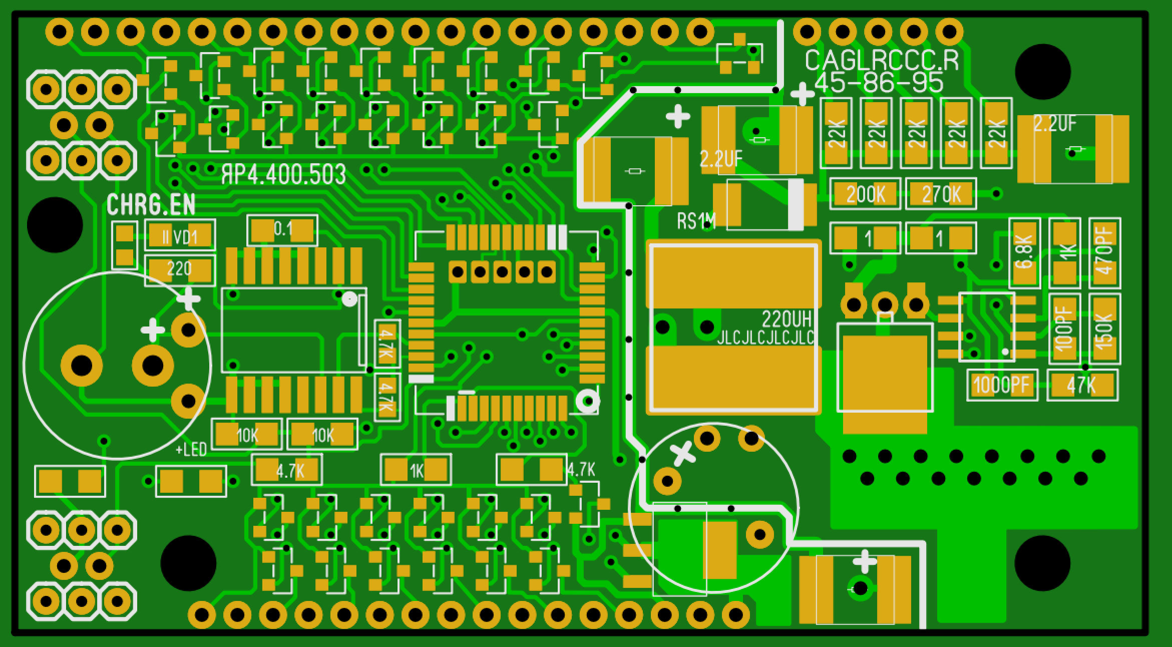
Can you post pictures of both PCB sides and cabling? Sure big caps will help. Better find the source of the problem.
Ioannis
Yes I can post, but the issue is that in both cases PCBs are different - it is thru hole (and big) components in one case, and small and SMD components in another, but giving the same issue. I think, maybe this is RMW issue somehow? because say PORTA.1 is used as ADC IN, but PORTA.2 is used as a digital output, has MPSA42 transistor connected to it's pin.
not at all likely , which pin is having its expected digitally "read back" value changed by a digital write to another pin on the the same port ?I think, maybe this is RMW issue somehow?
as ioannis suggests this is looks very much an EMI problem that could most likely could be ameliorated by having the switch circuitry of more suitable impedance and using appropriate adc conversion speed along with sample hold time and rate.
with no schematic or code to look at it might just be bad code who would know
Warning I'm not a teacher
Ok, here is the part of code which reads the keys:
here is PCBCode:adcin 7,ard if ard<130 then 'if any button is pressed ticker=ticker+1 'increase value and wait - debouncing pause 1 endif if ticker>150 and ard<100 then 'if left button is pressed then next menu item menuitem=menuitem+1 ticker=0 'reset debouncer endif if ticker>150 and ard<130 AND ARD>100 then 'if right button pressed, change the value CVLADI=CVLADI+1 if cvladi>ulim or cvladi<dlim then cvladi=dlim ticker=0
 Members who have read this thread : 1
You do not have permission to view the list of names.
 Posting Permissions
Bookmarks