 Re: Current sensor output modification. PIC or opamp or something else?

Originally Posted by
retepsnikrep

Thanks for that.
Alain. When you say 'If conversion' do you mean using a PIC?
I didn't think that would be quick enough
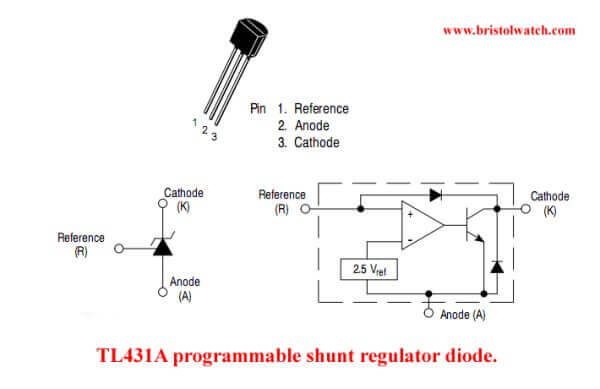
Or some sort of analog circuit like the TL431
Hi, Peter
I wrote = the number the ADC returns ...
Whatever processor you use ( of course, a PIC is much better ") )
)
Have a nice day
Alain
************************************************** ***********************
Why insist on using 32 Bits when you're not even able to deal with the first 8 ones ??? ehhhhhh ...
************************************************** ***********************
IF there is the word "Problem" in your question ...
certainly the answer is " RTFM " or " RTFDataSheet " !!!
*****************************************


Bookmarks