Code:
'*********************************************************************************
@ ERRORLEVEL -306 ; this command prevents the compiler to give you a notice of *
; crossing page boundary - make sure bits are set *
'*********************************************************************************
#CONFIG ; The PBP configuration for the PIC18F26K22 is:
CONFIG FOSC = INTIO67 ; Internal oscillator block
CONFIG PLLCFG = ON ; Oscillator multiplied by 4
CONFIG PRICLKEN = ON ; Primary clock enabled
CONFIG FCMEN = OFF ; Fail-Safe Clock Monitor disabled
CONFIG IESO = OFF ; Oscillator Switchover mode disabled
CONFIG BOREN = SBORDIS ; Brown-out Reset enabled in hardware only (SBOREN is disabled)
CONFIG WDTEN = ON ; WDT is always enabled. SWDTEN bit has no effect
CONFIG WDTPS = 32768 ; 1:32768 ---> HERE enable the watchdog timer with a 1:32768 postscale;|
CONFIG PWRTEN = ON
CONFIG HFOFST = ON ; HFINTOSC output and ready status are not delayed by the oscillator stable status
CONFIG MCLRE = EXTMCLR ; MCLR pin enabled, RE3 input pin disabled
CONFIG LVP = OFF ; Single-Supply ICSP disabled
CONFIG XINST = OFF ; Instruction set extension and Indexed Addressing mode disabled (Legacy mode)
CONFIG DEBUG = OFF ; Disabled
CONFIG CP0 = OFF ; Block 0 (000800-003FFFh) not code-protected
CONFIG CP1 = OFF ; Block 1 (004000-007FFFh) not code-protected
CONFIG CP2 = OFF ; Block 2 (008000-00BFFFh) not code-protected
CONFIG CP3 = OFF ; Block 3 (00C000-00FFFFh) not code-protected
CONFIG CPB = OFF ; Boot block (000000-0007FFh) not code-protected
CONFIG CPD = OFF ; Data EEPROM not code-protected
CONFIG WRT0 = OFF ; Block 0 (000800-003FFFh) not write-protected
CONFIG WRT1 = OFF ; Block 1 (004000-007FFFh) not write-protected
CONFIG WRT2 = OFF ; Block 2 (008000-00BFFFh) not write-protected
CONFIG WRT3 = OFF ; Block 3 (00C000-00FFFFh) not write-protected
CONFIG WRTC = OFF ; Configuration registers (300000-3000FFh) not write-protected
CONFIG WRTB = OFF ; Boot Block (000000-0007FFh) not write-protected
CONFIG WRTD = OFF ; Data EEPROM not write-protected
CONFIG EBTR0 = OFF ; Block 0 (000800-003FFFh) not protected from table reads executed in other blocks
CONFIG EBTR1 = OFF ; Block 1 (004000-007FFFh) not protected from table reads executed in other blocks
CONFIG EBTR2 = OFF ; Block 2 (008000-00BFFFh) not protected from table reads executed in other blocks
CONFIG EBTR3 = OFF ; Block 3 (00C000-00FFFFh) not protected from table reads executed in other blocks
CONFIG EBTRB = OFF ; Boot Block (000000-0007FFh) not protected from table reads executed in other blocks
#ENDCONFIG
;*---------------------------------------------------------------------------------------------------------|
;*---------------------------------------------------------------------------------------------------------|
'define I2C_SLOW 1
define OSC 64
INCLUDE "modedefs.bas"
INCLUDE "ALLDIGITAL.pbp"
OSCCON = %01110000 ; 16Mhz
OSCTUNE.6 = 1 ; Enable 4x PLL
while ! osccon2.7 :WEND ; to make sure the pll has stabilised before you run any other code
TRISA = %00000000
TRISB = %00000000
TRISC = %10011000
'----------------------- At start all PORTS LOW -------------------------|
'------------------------------------------------------------------------|
PORTA = 0 'make low all ports at A range |
PORTB = 0 'make low all ports at B range |
PORTC = 0 'make low all ports at C range |
PORTE = 0 'make low all ports at E range |
'------------------------------------------------------------------------|
'-------------------------- COMPARATORS OFF -----------------------------|
'------------------------------------------------------------------------|
CM1CON0.7 = 0 'Disable comparator1 |
CM2CON0.7 = 0 'Disable comparator2 |
'------------------------------------------------------------------------|
'*----------------------- | EUART 1 Configuration | --------------------------|
DEFINE HSER_RCSTA 90h ' Enable serial port & continuous receive
DEFINE HSER_TXSTA 24h ' Enable transmit, BRGH = 1
DEFINE HSER_CLROERR 1 ' Clear overflow automatically
DEFINE HSER_SPBRG 160 ' 38400 Baud @ 64MHz, -0.08%
SPBRGH = 1
BAUDCON.3 = 1 ' Enable 16 bit baudrate generator
'*-----------------------------------------------------------------------------|
ORANGE var LATA.2 ' ORANGE LED TO INDICATE POWER ON OF THE PIC
GREEN var LATC.0 ' BLUE LED TO INDICATE SENSOR WOKRING CONDITION
RED VAR LATC.5 ' RED LED TO INDICATE ERROR
SDA var portc.4 ' DATA PIN
SCL VAR portc.3 ' CLOCK PIN
;-------------------------------------------------------------|
;---------------------- variables ------------------|
;-------------------------------------------------------------|
Timeout cON 2000
i var byte
mydata var BYTE
fifowr var byte
fiford var byte
fifoD1 var byte
fifoD2 var byte
fifoD3 var byte
ContWR var byte ; $AE or b10101110
ContRD var byte ; $AF or b10101111
ContRD = $AF ; b10101111
ContWR = $AE ; b10101110
addr var byte ; this must be defined as variable word
'I2C_ID_ADDR con $57 ; 7-bit version of the above
'define I2C_ID_ADDR 57h ; 7-bit version of the above
;//register addresses
;---------------------- STATUS REGISTER -----------------------
REG_INTR_STATUS_1 var byte 'con $00
REG_INTR_STATUS_2 var byte 'con $01
REG_INTR_ENABLE_1 var byte 'con $02
REG_INTR_ENABLE_2 var byte 'con $03
;----------------------- FIFO REGISTERS -----------------------
REG_FIFO_WR_PTR var byte 'con $04 ; FIFO WRITE POINTER REG ADDR IS 0X04
REG_OVF_COUNTER var byte 'con $05
REG_FIFO_RD_PTR var byte 'con $06
REG_FIFO_DATA var byte 'con $07
;---------------------- CONFIG REGISTER -----------------------
REG_FIFO_CONFIG var byte 'con $08
REG_MODE_CONFIG var byte 'con $09
REG_SPO2_CONFIG var byte 'con $0A
REG_LED1_PA var byte 'con $0C
REG_LED2_PA var byte 'con $0D
REG_PILOT_PA var byte 'con $10
REG_MULTI_LED_CTRL1 var byte 'con $11
REG_MULTI_LED_CTRL2 var byte 'con $12
;----------------------- TEMP REGISTER -------------------------
REG_TEMP_INTR var byte 'con $1F
REG_TEMP_FRAC var byte 'con $20
REG_TEMP_CONFIG var byte 'con $21
REG_PROX_INT_THRESH var byte 'con $30
;----------------------- PART ID REGISTER ----------------------
REG_PART_ID var byte
' -----------------------------------------------------------------------------|
' -----------------------------------------------------------------------------|
' [ LCD Initialization ] |
'------------------------------------------------------------------------------|
' FIRST TIME BOOTUP: We give plenty of time for tbe LCD '
pause 1000
HSEROUT[$55] ' uOLED Initialize this is the 'U' character of autoband rate to LCD
Hserin timeout,error,[wait(6)]
HSEROUT [$45] ' clear the LCD
Hserin timeout,error,[wait(6)]
hserout[$73,$00,$03,$11,$ff,$ff,"HEART RATE SENSOR",$00]
Hserin timeout,error,[wait(6)]
Hserout[$4F,$01] ; Set Transparent-Opaque Text - 4Fhex
Hserin timeout,error,[wait(6)]
pause 500
HSEROUT [$45] ' clear the LCD
Hserin timeout,error,[wait(6)]
' indication of the working code
for i= 0 to 3
orange = 1
pause 100
orange = 0
pause 50
next i
orange = 1
init:
low green
low red
pause 100
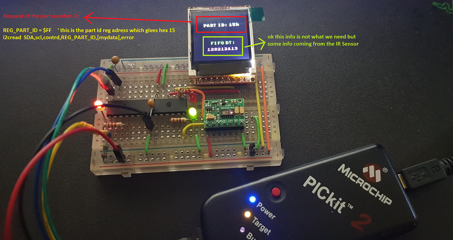
REG_PART_ID = $FF ' this is the part id reg adress which gives hex 15
i2cread SDA,scl,contrd,REG_PART_ID,[mydata],error
'*******************************************************************************
' if %00000010 is used then only IR LED for heart rate mode is set *
' if %00000011 is used then only RED & IR LED for SPO2 mode is set *
' if %00000111 is used then Multi Led Mode is set *
'*******************************************************************************
addr = $09 ' MODE CONFIGURATION
i2cwrite SDA,scl,contwr,addr,%00000010,error ' ModLED = $02 as per data sheet heart rate mode, $03 SpO2 mode
'pause 100
addr = $0C 'LED PULSE AMLIDUDE FOR for LED1_PA[7:0] 0x0C
i2cwrite SDA,scl,Contwr,addr,$3f,error' if LED1_PA = $3F , 12.6 mA , ($7F is 25.4 mA)
'pause 100
'********************************************************************************
REG_FIFO_WR_PTR = $04 ; FIFO WRITE POINTER REG ADDR IS 0X04
i2cwrite SDA,scl,contrd,REG_FIFO_WR_PTR,[fifowr],error
REG_FIFO_RD_PTR = $06 ; FIFO READ POINTER REG ADDR IS 0X06
i2cread SDA,scl,contrd,REG_FIFO_rd_PTR,[fiford],error
REG_FIFO_DATA = $07
i2cread sda,scl,contrd,REG_FIFO_DATA,[fifod1,fifod2,fifod3],error
'********************************************************************************
start:
HSEROUT [$73,$03,$04,$11,$ff,$ff,"PART ID: ",hex mydata,"h",$00]
Hserin timeout,error,[wait(6)]
HSEROUT [$73,$05,$0A,$11,$07,$E0,"FIFO DT: ",$00] ' lime color $07,$E0
Hserin timeout,error,[wait(6)]
HSEROUT [$73,$04,$0C,$11,$F8,$1F,dec fifod1,dec fifod2,dec fifod3,$00] ' fuchsia color $F8, $1F
Hserin timeout,error,[wait(6)]
'goto start
blueled:
high green
PAUSE 300
goto init
error:
high RED
pause 100
end


Bookmarks