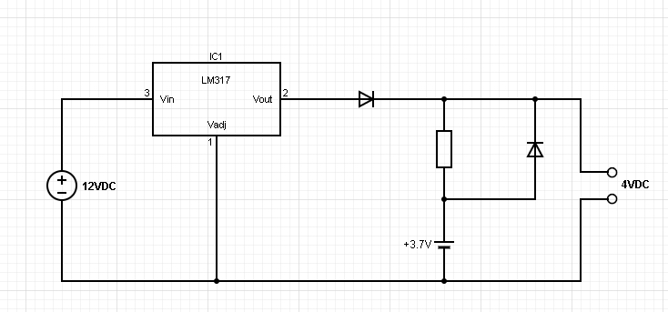
 Re: Battery power back-uped circuit
Hi, Flotul,
Those BMS are not always installed ...
I have dozens of LiPo / LiFe batts home and only one has it included ... so, consider it's not mandatory !!!
sometimes, there's only a fuse !!!
Alain
************************************************** ***********************
Why insist on using 32 Bits when you're not even able to deal with the first 8 ones ??? ehhhhhh ...
************************************************** ***********************
IF there is the word "Problem" in your question ...
certainly the answer is " RTFM " or " RTFDataSheet " !!!
*****************************************


 ), it doesn't get inside my head that easy.


Bookmarks