

I'm trying to use PWM within a circuit that handles an audio signal. It's creating a lot of high frequency noise. I'm using a 16F684. I've tried separating the analog and digital ground planes. Does anyone have any recommendation for things to try?

I'm trying to use PWM within a circuit that handles an audio signal. It's creating a lot of high frequency noise. I'm using a 16F684. I've tried separating the analog and digital ground planes. Does anyone have any recommendation for things to try?

I'm certainly no expert but can you show the schematic and PCB layout? It might give a better sense of what you're doing.
I mean, are you dimming a LED or running an 500A TIG inverter with that PWM signal....
Try finding out where the noise is comming in. Is it on the power rail(s) or on the signal lines (or both)?
Add more decoupling/filtering on the power rails of the OP-amps or whatever it is that's handling the audio signal. Think carefully about how you're routing your PCB.

Software wise you might try increasing the frequency you're using for your PWM. Above 20kHz the ear can't really hear it. The PBP3 Reference Manual sets a 32767 Hz upper limit for the HPWM command. Working the CCP & TMR2 registers manually, you may be able to go higher.
I was hoping there was a solution in the software and not the hardware. I've seen other similar projects where they used the same PIC16F684 but used a 20MHz external crystal higher frequencies.Originally Posted by mpgmike

I'm no expert, but most analogue audio signals alternate between + and - rails and thus are not "grounded" in the same way as supply rails. But you have said that separating them hasn't resolved the problem. Possibly some grounded shielding over the PIC to prevent RF interference might help
This is always caused by either the design or layout. Post the schematic and layout if you really want an answer.
It seems to be in the ground. Even so much as sharing the ground with shielded coax where the signal isn't even going anywhere near the MCU still has noise.
To make this as simple as possible, all this is, is a 5v power supply, a PIC, and two 1/4" jacks that share ground. The PIC is only connected to +5v and ground. The CCP1 pin isn't connected to anything. This is on a breadboard. I am getting a lot of noise that goes up and down in pitch as the duty cycle goes up and down.
Code:Duty var byte Main: For Duty = 0 to 255 ' Gets brighter pause 100 PWM 1, Duty, 1000 Next Duty For Duty = 254 to 0 step -1 'Gets dimmer pause 100 PWM 1, Duty, 1000 Next Duty Goto Main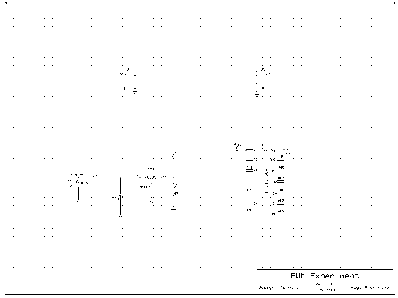
I would add a 0.1 uF cap to the output of your 78L05. I've had noise issues that affected the power supply, which in turn affected everything. A simple .1 ceramic cap fixed a multitude of gremlins.
What are you using to connect to the jacks, how far apart are they, what does the board layout looks like, is there a ground plane, is there a decoupling cap on the PIC, how does the 9V ground relate to whatever you have connected, and probably a few more questions once you answer these. There are pretty sharp edges on the steps, so you may be generating RF that is rectified by whatever you are using to listen to audio.

Where is the .1Uf decoupling cap directly at the PIC power pins?
Dave Purola,
N8NTA
EN82fn
I added at .1uF to the 5v and that did seem to reduce the noise a bit. Not to an acceptable level, but it did help.

Add capacitors close to noise source(right across pin of PIC). 1,10 and 100nF in parallel.
Also Breadboard have large capacitance between 2 rows of pin. Try to put ground next to PWM pin.
Use short leads, as stray inductance plays large role. Also try to create star ground point.
I'm using a small bread board. The PIC and power supply are on one side of the bread board. The jacks are on the other side. The jacks are your typical enclosed 1/4" stereo jack like a Switchcraft 112BX. I'm using some higher end shielded instrument cables to connect to a guitar and a little test amp on my bench.

Let this be from me:
Harmonics are generated at the latest ground pin (or say final gnd connection of power supply; the return point). Usually, this is minimized by collecting all gnd points inside the circuit at one final point and then connect this final point to the gnd of power supply through an inductor serially connected in between.
Crucial point is that, power supply gnd must first go through inductor and then be connected to your final gnd point of audio circuit .
Try different values of inductor until you get your best result.

"If the Earth were a single state, Istanbul would be its capital." Napoleon Bonaparte
Hi keithv,
I just discover your post right now.
I do not see any writings about the RC integrator circuit which should take place between your CCP1 output and the audio input. This RC network eliminates most your sampling signals.
In my application I use R = 1k and C = 47nF for a sampling rate of 56 kHz and this works fine.
You should modify the values accordingly, for example C should be about 120 nF for a sampling rate of 20 kHz.
Best regards
MikeBZH

What everyone else says, plus:
Declare a ground star point and make all grounds radiate from that point - no daisy chains.
You should be able to trace ground noise origin with a scope.
Electrolytic caps are the bastard love child of a car battery and an RF antenna, replace with tant or ceramic if you can.
Also, make sure all caps are low ESR/ESL like TY.
Thanks for all the suggestions. I've been sidetracked by another project, but I will revisit this and give them a try and let you know how it works out.
 Members who have read this thread : 0
You do not have permission to view the list of names.
 Posting Permissions
Bookmarks