

Hello all around!
I tried to put a EAGLE schematic attachment into this and I got the answer "Invalid file". How do I convert an Eagle document? I have to save PBP docs into txt format to post them. Is there anything like for EAGLE ?
regards
Mugel

Hello all around!
I tried to put a EAGLE schematic attachment into this and I got the answer "Invalid file". How do I convert an Eagle document? I have to save PBP docs into txt format to post them. Is there anything like for EAGLE ?
regards
Mugel

In EC mode the clock out on RA6 is FOSC/4, so with 20MHz on CLKI, CLKO will be 5MHz
To post the schematic, either make a screen dump and post the image or print/export to .pdf and post that.
I was going to say exactly what tumbleweed just did so now I won't, but I'll say this:
Is it an actual oscillator (not a crystal or resonator) then you should be able to drive both PICs directly from the output of the oscillator but check the datasheet for the oscillator, I believe you can use either HS or EC mode for this.
/Henrik.
Hello Henrik,
I´ll try to get the image. No didn´t work, had 8MB Picture max is 1 MB.
Old Farts and Computers,
here we go...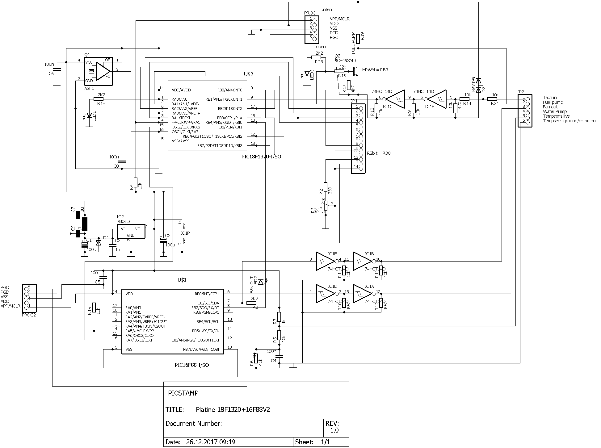
OK, so it is a proper oscillator.
Then just drive both PICs directly from it it. The way you have it now the second PIC will run at 1/4 the speed of the first one.
Use .png instead of .bmp for images like this, much better!
/Henrik.
Made several mistakes, killed one 18F1320 don´t know how , destroyed my PICKIT operating system, had to desolder and solder one 18F1320, BIG Mistake in the schematic: I had to use the lower 4 bits of PORTA and these begin at PORTA0 not PORTA1 . Put a resistor between 74HC14 and RB1 otherwise the PIC may be grilled.
Changed config:
#CONFIG
CONFIG OSC = HS ;Clock out on RA6 :1/1 CLKI
#ENDCONFIG
now the second PIC gets the same frequency out of the first PIC. Checked it with a scope.
Hardware seems to work (if nothing else is grilled) and I can jump into software.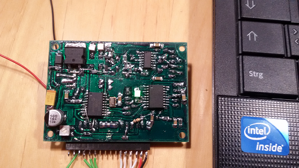
 Members who have read this thread : 0
You do not have permission to view the list of names.
 Posting Permissions
Bookmarks