

As long as you don't say you wrote it ... you can do whatever you want with it.Originally Posted by Glenn

For Free!
<br>


As long as you don't say you wrote it ... you can do whatever you want with it.
For Free!
<br>
DT

Hi darrel.. Really nice work.Congrats.
I intend to write lcd bar vu-meter and bar voltmeter codes. I did for voltmeter but not for bar vu-meter. And I need help for this. MCU is 16f876 and 2x16 lcd.. I need some help to convert reading from frequency to the bars. Can you help me ?
For VU-Meter, I think you'll need an external LOG convertor such as one of these op-amp circuits ...
http://en.wikipedia.org/wiki/Operati...rithmic_output
http://www.st-andrews.ac.uk/~www_pa/...rt8/Page3.html
Without the LOG convertor, you'll only see big peaks in the bargraph and none of the lower level signals.
If you're thinking of a Spectrum Analyzer, then nope, can't help there.I need some help to convert reading from frequency to the bars
<br>
DT

I use the Bargraphs(lines) to show on lcd the volt from 0 to 5 volt with adc 10 bit.
How to change the code to show always at first Col the first character.
Like this : from ||||| to show only | if the volt is 0.
Hi Ioannis. (Γεια σου Γιάννη)
Can you post the shematic of ca3089 which you used?
Someone to help;
If I understand the question, maybe ...
ADvalue = ADvalue MAX 18
That will limit the value to a minimum of 18, which should always leave 1 line showing.
Assuming a 20 character bargraph, with a range of 1023.
hth,
DT
I want if the value is 0 (0-1023) to show like this picture:
I forgot to send the diagram for the CA3089. Sorry... I will soon.
Now about the bar at 0, why not put an IF-THEN statement after ADC subroutine to test if the ADC result is 0.
Or the more elegant Darrel's solution. Same result.
Ioannis

Unfortunatly CA3089 seem to be discontinued, and hard to get, well, tehre are a few on ebay, but more common places seem to be out of stock ?
I would love to see the schematics you used anyway Ioannis.
On the attached check page 8-29 the up left schematic. Output is on pin 13 and there is no need for coils etc as that part is not needed. In fact no components are needed on the pins 5,6,7,8,9,10,12 and 15.
On 13 there must be a load resistor to get the output voltage and on input pin 1 the capaciotors from .01 and .02 should be large enough for the audio spectrum as the values shown are for 10,7MHz IF. Put 10 or even 100 uF to get decent low freq. response. The chip works from almost 0 Hz!
Ioannis
Last edited by Ioannis; - 7th February 2010 at 12:27.
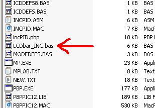
I have a problem with this program.I made everything,put the .bas file in the same folder where the program is.But when I compile it,it says that I have a WARNING: Unable to open INCLUDE file LCDBAR_INC.BAS. I made a extension .bas file for the Include file and it's not workingany sugestion?
Hi,
It works perfectly fine here. Make sure you have the file in the correct folder (either in the same folder as your source file or in the PBP folder). Also make sure that the actual filename, including extension, matches exactly what it says in the code.
INCLUDE "LCDBar_INC.bas"
The filename should be LCDBar_INC.bas but when you download it from the first post in this thread it's LCDBar_INC.bas.txt and you need to remove the .txt from the end.
/Henrik.
I did that,but it's not working.When I make an extension of the .txt file in .bas file I go File> Save as.. and File name:LCDbar_INC.bas.bas Save as type:All files Encoding:ANSI
Is there a problem?Am I Ок?
Last edited by SKOLS1; - 28th January 2011 at 10:47.
There's no need to open that file. Just right-click on it, select rename and remove the .txt extension - don't add another .bas extension.
Make sure that the filename is LCDBar_INC.bas Not LCDBAR_INC.bas.txt or LCD_Bar_Inc.bas.bas or anything else - just LCDBar_INC.bas
Last edited by HenrikOlsson; - 28th January 2011 at 11:18.
I have a problem when i compile the code.It says this:
WARNING Line 1: Bad token "ï".
WARNING Line 1: Bad token "»".
WARNING Line 1: Bad token "¿".
What code exactly is it you're trying to compile? I've tried compiling LCDBar_INC.bas by itself as well as INCLUDED from another program and it compiles just fine.
Post the code you're trying to compile and we'll take a look.
I compile the first code: LCDbar_AD_Demo.bas.txt and when I save as I save it in a new folder,the include file I save at in the folder where the first code is.Where I get wrong?
I just downloaded the code (LCDbar_AD_Demo) from the second post and it compiled just fine.
The code tries to set the CONFIG bits so for now, try commenting out or deleting the very first line:I don't think this is the problem but I hope so because if it's not I have no idea :-(Code:' @ __CONFIG _CONFIG1H, _OSCS_OFF_1H & _HS_OSC_1H ' <-- Comment this line. Set oscillator to (HS)
I'am so angry cause I can't compile the code.Can somebody compile it and put the hex file on the forum,then I can download it and program the PIC with it.I use 2*16 LCD display.
Hi,
In order to compile it for you we must at least know which PIC you're using and what you're oscillator speed is.
Which version of PBP are you trying to compile this with and for which PIC?

Did you try the bar graph code that I have posted at the beginning of this thread? it is standalone and no include files to worry about, no need to download just copy the code and paste it.
You can't teach an old dog new tricks, but I'm always willing to try.
I fix the problem with the extension of the file LCDbar_INC.bas, but now I have this problem I compile the code but can I use 2*16 LCD display?I use PIC16F887 @ 20MHz
Last edited by SKOLS1; - 29th May 2011 at 12:45.

Sure you can.
Steve
It's not a bug, it's a random feature.
There's no problem, only learning opportunities.
But now it's working,baragraph isn't showing on the LCD display,just Value: 1,2 etc.
I use 2*16 LCD display.Should I change the code in LCDbar_INC.bas
Must be intranet interference, my crystal ball refuse to give me your code, could you post your code here and PIC model, so we could see what's wrong with?
Steve
It's not a bug, it's a random feature.
There's no problem, only learning opportunities.
define OSC 20
CLEAR
INCLUDE "LCDbar_INC.bas" ' Include the BARgraph routines
' Define LCD connections
DEFINE LCD_DREG PORTB ' LCD Data Port
DEFINE LCD_DBIT 0 ' Starting Data Bit
DEFINE LCD_RSREG PORTB ' Register Select Port
DEFINE LCD_RSBIT 4 ' Register Select Bit
DEFINE LCD_EREG PORTB ' Enable Port
DEFINE LCD_EBIT 5 ' Enable Bit
DEFINE LCD_BITS 4 ' Data Bus Size
DEFINE LCD_LINES 2 ' Number of Lines on LCD
DEFINE ADC_BITS 8 ' Number of bits in ADCIN result
ADCON1.7 = 1 ' Right Justify AD result
Value VAR WORD ' Must be a WORD even though AD is 8bit
LCDOUT $FE, 1 ' Clear Screen
PAUSE 200
Loop1:
ADCIN 0, Value
LCDOUT $FE,2,"Value = ",DEC Value," "
; syntax- BARgraph Value, Row, Col, Width, Range, Style
@ BARgraph _Value, 2, 0, 16, 255, lines
Goto Loop1
END
I use PIC16F877 @ 20MHz(I use 8 MHz,too) I delete the frist line because there is an error in compiling
Hopefully someone smarter than me can figure this out. Darrel, this program is awesome by the way!
I'm using an OLED screen and Darrel's anypin LCD program. The OLED screen works perfectly with the data displayed but not with bargraph program. Anyhow, have a for-next loop counting to 512. It runs perfectly up until 32 or so and then displays strange stuff until it hits 99 then it's good again until about 155 then bad again until about 222 then good again until 272 then bad until about 342 then good until about 388 then bad until about 462 and then it goes to 512 and loops back around. The program looks like this:
Code:DEFINE OSC 48 include "LCDBAR_INC.PBP" '=============================================================================== ' OLED CHANGE '=============================================================================== '===============================ENABLE FOR CAR PROGRAM==========================' LCD_DB4 VAR PORTE.0 LCD_DB5 VAR PORTE.1 LCD_DB6 VAR PORTE.2 LCD_DB7 VAR PORTA.4 LCD_RS VAR PORTB.6 LCD_E VAR PORTB.7 '================================================================================ LCD_Lines CON 2 ' # of Lines on LCD, 1 or 2 (Note: use 2 for 4 lines) LCD_DATAUS CON 50 ' Data delay time in us LCD_COMMANDUS CON 2000 ' Command delay time in us INCLUDE "LCD_AnyPin.PBP" ; *** Include MUST be AFTER LCD Pin assignments **** ' ============================================================================== ' CONFIGS '=============================================================================== @ __CONFIG _CONFIG1L, _PLLDIV_5_1L & _CPUDIV_OSC1_PLL2_1L & _USBDIV_2_1L @ __CONFIG _CONFIG1H, _FOSC_HSPLL_HS_1H & _FCMEN_OFF_1H & _IESO_OFF_1H @ __CONFIG _CONFIG2L, _PWRT_OFF_2L & _BOR_OFF_2L & _BORV_3_2L & _VREGEN_ON_2L @ __CONFIG _CONFIG2H, _WDT_OFF_2H & _WDTPS_32768_2H @ __CONFIG _CONFIG3H, _CCP2MX_ON_3H & _PBADEN_OFF_3H & _LPT1OSC_OFF_3H & _MCLRE_ON_3H @ __CONFIG _CONFIG4L, _STVREN_ON_4L & _LVP_OFF_4L & _ICPRT_ON_4L & _XINST_OFF_4L '============================================================================== ' SETTINGS ' ============================================================================== '76543210 '76543210 TRISA = %00100110: PORTA = %00000000 TRISB = %00010001: PORTB = %00010000 TRISC = %00000000: PORTC = %00000001 TRISD = %11011100: PORTD = %00000000 TRISE = %00010000: PORTE = %00010000 ADCON0 = %00000001 CMCON = 7 SSPSTAT = %01100100 SSPCON1 = %00100001 BAUDCON = %00001111 ADCON1=15 CCP2CON = %00011100 'changed on 11/16/12 CCP1CON = %00011100 'changed on 11/16/12 X VAR WORD MainLoop: FOR X=1 TO 512 PAUSE 100 LCDOUT $FE,148,DEC X," " '@ BARgraph Value, Row, Col, Width, Range, Style @ BARgraph _X, 1, 0, 20, 512, lines NEXT X GOTO MAINLOOP
I've tried a bunch of stuff (changing the parameters on the @ bargraph line but nothing seemed to help. This is the OLED screen I'm using:
http://www.newhavendisplay.com/specs...420DZW-AY5.pdf
Everytime I hear Newhaven, I cringe.
Here's your program running on a 4550 at 48Mhz in the simulator.
So I don't think it's a programming issue.
It could be an R-M-W problem.
Is the LCD connected via a ribbon cable? If so how long?
Have you tried running the CPU at 20Mhz without the PLL?
Or it could be just another Newhaven issue.
Have you tried a normal LCD?
DT
I did a lot of testing last night and it does appear to be the OLED screen that has issues. I have two OLED screens mounted on two different pieces of equipment and with the code above they do the same thing. I then put a standard LCD screen (2X16) through the same tests and it worked perfectly. I now have more questions than answers.
Why? They work perfectly with displaying letters and numbers and the OLED screen is so much better than an LCD screen. I'm guessing you've had problems with them in the past?Everytime I hear Newhaven, I cringe.
That thing is pretty cool. Where can I get it?Here's your program running on a 4550 at 48Mhz in the simulator.
After some testing, here is some information that may be useful.........or may not be. With the following line of code:The software will work perfectly from 0 to 33. If I use a For/Next routine for 0-33, it will run with no problems for hours on end (I know it will, trust me!) When I put 0-34, it flakes out when it gets to 34 and only 34. When it rolls back around, the same thing happens. 0-33 works good and then 34 won't, up until 98 or so. I don't get that.Code:@ BARgraph _X, 0, 0, 20, 512, lines
By changing to the following code:Now 0-110 works perfectly. The only thing I did was move the column from 0 to 1! Riddle me that one!Code:@ BARgraph _X, 0, 1, 20, 512, lines
Also, if I just change to this codeNow it will count much higher without a problem.@ BARgraph _X, 0, 1, 20, 10000, lines
Last edited by Christopher4187; - 21st November 2012 at 11:24.

Wow, is that thing slowwwwwwww. 600uS. for just about any of the control instructions? I really think you need to check your command and data delay settings. If I was using it I would also operate it in 8 bit mode. Twice as fast..... I also suggest reading the busy flag because if you are not then you are probably sending it instructions while it is executing the last instruction.
Last edited by Dave; - 21st November 2012 at 12:52.
Dave Purola,
N8NTA
EN82fn
If the command and data delay settings are wrong or the device is too slow, why does it work perfectly with displaying letters and numbers? In addition, I could put a for/next loop from 0 to 33 and the bargraph routine runs perfectly hours on end. More testing reveals this:
Range.... Number where the bargraph is not displayed correctly
64 .... 4
128 .... 8
256 .... 16
512 .... 34
1024 .... 66
2048 .... 132
This means something, just not sure what. The one common thing I can see is that when one box (three vertical "l"'s) fills up, the next time the bargraph routine attempts to write to the next box, it will fail. If I adjust the column from 0 to 1, it will now allow me to successfully write four boxes instead of one.
Maybe that is all it is good for?why does it work perfectly with displaying letters and numbers?
Dave
Always wear safety glasses while programming.
A vast majority of people that call tech support with LCD problems, are using Newhaven displays.
It doesn't seem to matter what type (LCD, OLED, COG).
But i agree with Dave, the timing requirements are ridiculous.
It's even 600 uS for data transfers (per nibble) according to the datasheet.
Try changing to this ...Code:LCD_DATAUS CON 600 ' Data delay time in us (was 50)
DT
C'mon, man! We don't give up that easily!Maybe that is all it is good for?
It's not a timing issue because it runs fine at 25uS or 1000uS. I've found a conflict with the "LCDbar_INC" program and the OLED screen. When the LCDbar program attempts to write to even columns, it displays wacky stuff. When it writes to odd columns, it works like a champ! I'll explain more in detail when I get home from work.
I got it working.....sort of....
Last edited by Christopher4187; - 21st November 2012 at 18:13. Reason: Additional info
Life is too short to play with junk. Yes, I would give up and get a unit that works.C'mon, man! We don't give up that easily!
Dave
Always wear safety glasses while programming.
I'm not smart enough to figure out why this is happening but the problem has been identified. Whenever the program sends "Threebars," it goes wacky. If I modify the code from this:
to this:Code:SELECT CASE BARtemp CASE IS > BARloop LCDOUT ThreeBARS ; send 3 bars ||| CASE IS < BARloop
it will run fine. Of course only two bars will be displayed but something with the code is causing a problem in the display.Code:SELECT CASE BARtemp CASE IS > BARloop CASE IS < BARloop
I made a bargraph routine and it works just fine so the problem is a conflict between the lcdbar inlcude file and the OLED screen. There isn't enough experience in my brain to figure out why so maybe someone else can. It was a good experience for me because I never used bargraphs before and I learned a lot from DT's program. The only thing I don't like about the program below is that it keeps writing over the previous graph, even if the data doesn't change, so if the bargraph stays at 100% or a high amount, you can see the bargraph flicker a little bit. I'm guessing that a routine is needed whereby nothing is written unless the number changes.
Code:C0 VAR BYTE C1 VAR BYTE C2 VAR BYTE C3 VAR BYTE C4 VAR BYTE C5 VAR BYTE C6 VAR BYTE C7 VAR BYTE C0 = $40 C1 = $48 C2 = $50 C3 = $58 C4 = $60 C5 = $68 C6 = $70 C7 = $78 lcdout 254,C0,REP 16\8 lcdout 254,C1,REP 24\8 lcdout 254,C2,REP 28\8 lcdout 254,C3,REP 30\8 lcdout 254,C4,REP 31\8 BOX VAR WORD LINE VAR WORD FRICT_PAD_TQ_BAR VAR WORD LINE_DISPLAY VAR BYTE BOX_DISPLAY VAR BYTE FRICT_PAD_TQ VAR WORD MAIN: FRICT_PAD_TQ_BAR=(FRICT_PAD_TQ-12)/5 BOX_DISPLAY=127 LINE_DISPLAY=0 FOR LINE = 0 TO FRICT_PAD_TQ_BAR LCDOUT $FE, BOX_DISPLAY,LINE_DISPLAY LINE_DISPLAY=LINE_DISPLAY+1 IF LINE_DISPLAY=5 THEN BOX_DISPLAY=BOX_DISPLAY+1 LINE_DISPLAY=0 ENDIF LCDOUT $FE,212, DEC FRICT_PAD_TQ_BAR NEXT LINE BOX_DISPLAY=0 LINE_DISPLAY=0 GOTO MAIN
Chris, Have you written code to look at the BUSY bit? I think you would be a bit supprised to find out just how long it takes some SPOOLED commands to execute. I have had this problem before with some NewHaven displays and with there lack of documentation you just have to figure out things on your own. What I would do is, write a routine to first set an output bit and connect a scope, then look at the busy bit after you send a command string to the display. re-check the busy bit to be clear, reset the output bit when the bit is clear and you would be supprised. Why do you think they make it available? You as the programmer are supposed to knowlegable enough to use the BUSY bit. Otherwise, don't complain about someone elses routines not working unless you know what the problem is....... Happy Thanksgiving......
Last edited by Dave; - 23rd November 2012 at 00:26.
Dave Purola,
N8NTA
EN82fn
It wasn't a complaint, Yoda. I said there was a conflict between DT's program and the OLED screen. That's a factual statement. In fact, I'm very appreciate of the information Darrel posts on here. Exhibit A:Otherwise, don't complain about someone elses routines not working unless you know what the problem isI've been using the OLED screens for over a year now. I know people have had problems with the displays but I really like them and never had a problem. If you know of a better OLED screen, by all means a better suggestion is always welcomed. Do you think people on here use Newhaven LCD/OLED screens? I'd be inclined to say yes. Given that fact, someone along the way is going to run into this same problem.Darrel, this program is awesome by the way!
I learned a lot from DT's program.
If there's a simple solution or a new line of code can be inserted to make it work correctly, why not do it? The main intent of the post was to elicit substantive discussion regarding the Newhaven OLED screen and DT's program. It doesn't work "off the shelf," which is perfectly fine. However, if Darrel or anyone else can provide a solution to make the program work, that would be great, but everyone on here understands there are no obligations. I don't have enough programming knowledge to contribute a lot here, so maybe this is a chance for me to do so if nobody else has the time to do it.
Personally, a lot of time has been spent on this and I'm really learning a lot. Even if I don't find a solution, it's time well spent.
 Members who have read this thread : 2
You do not have permission to view the list of names.
 Posting Permissions


Bookmarks