 38Khz IR carrier - best way to turn it on and off
I bought my wife a Roomba for Christmas. The one I got has one 'virtual wall' with it. The virtual wall allows you to place it inside a doorway, for example, and it emits an IR signal the the machine won't cross - you can stop it from going into the room. You can buy more of these virtual walls, but, of course, I would rather build one.
In searching robotics forums, it would appear that the virtual wall is a 38Khz carrier, turned on and off at 1ms intervals.
I'm just starting to experiment, so I may be WAY off here - but I just used an 18F2550 that I happen to have breadboarded, right now, and did the following:
When I put the scope on it, I got 38KHz (a little over, actually) and a period of 26uS (38KHz is actually 26.3uS). So probably, that will be close enough to work - I can't imagine the receiver on the robot is too fussy, but I'll have to try it.
Then, to get the 1mS on and off, I decided to just switch the pin from output to input and back again. Not sure why I have to use 500uS on one pause and 1000uS on the other pause, but the scope shows what I wanted for times. So I came up with:
Code:
MAIN:
	HPWM 1, 254, 38000
        pauseus 500
        TRISC.2 = 1
        pauseus 1000
        TRISC.2 = 0
	GOTO MAIN
And the attached picture is what the scope shows (not an expensive scope by ANY means). My question is after the image.
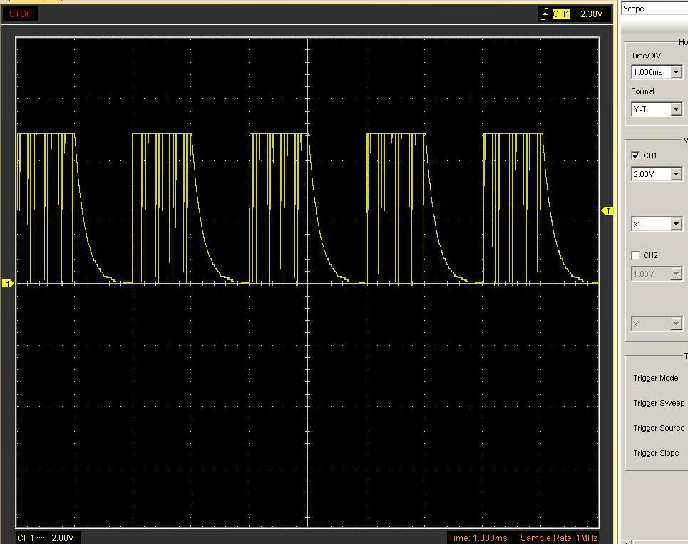
Any idea what that slope is as the port is switched from output to input? Any way to get rid of it? Or am I just on the wrong track here?
Thanks
Andy
"I have noticed that even those who assert that everything is predestined and that
we can change nothing about it still look both ways before they cross the street"
-Stephen Hawking


Bookmarks