


I specifically used 2 extra diodes to avoid any of the capacitance problems I'd have had using the same positive that supplies the regulator. In theory the main part of the circuit shouldn't interfere with the zero crossing part (not that much anyway).
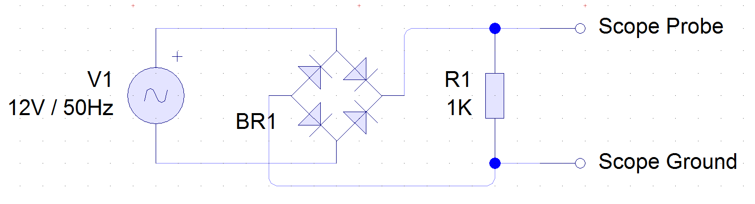
The schematic I posted above is just a guide for what my circuit looks like. The scope readings were all taken from the test circuit which I've attached below. There's nothing that should interfere with it at all. This test circuit doesn't have any capacitors or regulators or anything, just diodes and now a resistor.


Bookmarks