Hi 
I was looking through your version and come across this again, as is also in DTís original code:
Code:
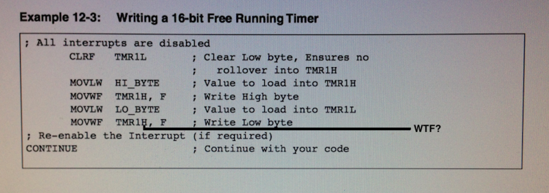
; -----------------  ADD TimerConst to TMR1H:TMR1L
ADD2_TIMER   macro
    CHK?RP  T1CON
    BCF     T1CON,TMR1ON           ;  1 InstCycle, Turn off timer
    MOVLW   LOW(TimerConst)        ;  1 InstCycle
    ADDWF   TMR1L,F                ;  1 InstCycle, Reload timer with correct value
    BTFSC   STATUS,C               ;  1 or 2 InstCycles
    INCF    TMR1H,F                ;  1 InstCycle
    MOVLW   HIGH(TimerConst)       ;  1 InstCycle
    ADDWF   TMR1H,F                ;  1 InstCycle
    endm
I am wondering about a few things like why this is here:
Code:
BTFSC STATUS,C ; 1 or 2 InstCycles
Depending on the carry status after the add, we would still have 8 instructions, because if the skip takes
two instructions, it skipped a line that would have taken another instruction.
I donít understand why itís necessary. If the ISR is called on timer overflow, then even if it is not zero
by the time itís reset, it should be a known value, and not have to be checked.
This somehow looks like itís setup as if the ISR was called a variable time after the overflow interrupt which should never happen.
I think there is something Iím not seeing, and the code it so simple, there must be a reason, otherwise itís easily fixed.
Iím seeing error when I use a 10MHz crystal to generate a 1Hz LED pulse, and get it roughly synced (visible to Human) with
the output of a GPS pulse per second signal. After an hour I can see a difference between the two blinking LEDs,
which for a Human to see, would probably take some ms difference.
There could be error in my code, but I doubt that as I have only interfaced with DTís timer,
or I have a terrible crystal, or board layout (very likely because the crystal is mounted to a two pin header to make it removable,
or crystals just really are that bad.


Bookmarks