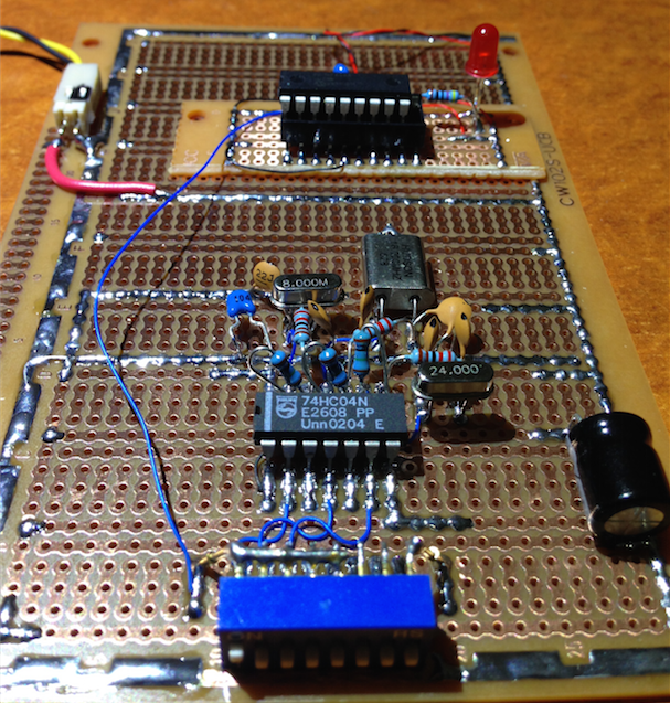
DT’s Elapsed Timer Magic Trick


Closed Thread
Results 1 to 22 of 22

Hybrid View

  1. #1
    Join Date
    Apr 2011
    Location
    Welches, Oregon
    Posts
    198


    Did you find this post helpful? Yes | No

    Default Re: DT’s Elapsed Timer Magic Trick

    I am a total noob, but I feel such cleverness deserves a guess - even if only to prove how far superior your skills. I am unwilling to just shrug and wait for you to reveal your skill without so much as voicing the consideration I have given - not so much a joke, but puzzle - you have provided.

    I will guess that there is some capacitance in the circuit and that you use some application of the RCTime constant as a reference; different clocks would, I think, reveal the clock speed by the timer values measured when charging and discharging a capacitor from a known voltage. I take my guess from watching the LED (which, I believe has a capacitance associated - and conveniently a resistor in series) which is slow to start - I'm hoping, because it is busy measuring...

  2. #2
    Join Date
    Aug 2003
    Posts
    985


    Did you find this post helpful? Yes | No

    Default Re: DT’s Elapsed Timer Magic Trick

    Interesting idea, but not tested by me so I don’t know if it would work

    The virtue in what I’m doing is someone might come up with a better way,
    and at the moment I would appreciate that.
    It’s not genius trust me, you’ll find out. Someone is close on another forum.

  3. #3
    Join Date
    Jan 2005
    Location
    Montreal, Quebec, Canada
    Posts
    3,172


    Did you find this post helpful? Yes | No

    Default Re: DT’s Elapsed Timer Magic Trick

    2015 nominee for best computer generated animations.

    Robert

  4. #4


    Did you find this post helpful? Yes | No

    Default Re: DT’s Elapsed Timer Magic Trick

    628A has two internal clocks

  5. #5
    Join Date
    Aug 2003
    Posts
    985


    Did you find this post helpful? Yes | No

    Default Re: DT’s Elapsed Timer Magic Trick

    I know of the 4MHz RC clock. What’s the other?

  6. #6
    Join Date
    Aug 2003
    Posts
    985


    Did you find this post helpful? Yes | No

    Default Re: DT’s Elapsed Timer Magic Trick

    It got figured out on another forum. A better way actually, without writing to the on-chip EEPROM at all.

    Code:
    '***********************************************************************************
    '*                                                                                 *
    '*                    Microchip Pic 16F628 @ 8,16 or 24MHz                         *
    '*                                  Art 2015                                       *
    '*                                                                                 *
    '*                          [email protected]                               *
    '*                                                                                 *
    '***********************************************************************************
    '
    '
    DEFINE OSC 20								'
    DEFINE NO_CLRWDT							'watchdog is cleared manually
    '
    INCLUDE "Elapsed.bas"							‘modified to take a variable
    '
    ' execution time!
    '
    '
    percount var byte							'
    wrtcount var byte							'
    clkvalue var byte							'
    xdata var byte								'
    'oscfreq var word							‘this is declared in Elapsed Timer file
    notreset var bit							'
    '
    CMCON = 7									'set ports digital
    trisb.4 = 0									'set led output
    portb.4 = 0									'
    '
    percount = 0								'
    clkvalue = 0								'
    '
    '
    notreset = status.bit4						'check wdt reset occured - 0 is did reset
    '
    '
    if notreset = 1 then						'was not reset by watchdog
    portb.4 = 1									'turn led on
    for percount = 0 to 255						'do eeprom writes until wdt reset
    pause 100									'
    write percount,$00							'
    next percount								'
    makereset:									'failsafe to make reset occur
    @ nop										;
    goto makereset								'
    else									'was reset by watchdog
    @ clrwdt									;clear the watchdog from now on
    wrtcount = 0								'reset write counter
    countwrites:								'count eeprom writes
    read wrtcount,xdata							'read byte
    @ clrwdt									;
    pause 10									'
    if xdata != $00 then						'
    goto donecount								'exit counting loop
    endif										'
    wrtcount = wrtcount + 1						'increment count
    goto countwrites							'
    donecount:									'
    for percount = 0 to 255						'erase the eeprom for next time
    pause 10									'
    @ clrwdt									;
    write percount,$FF							'
    next percount								'
    endif										'
    '
    'gosub flashout								'for testing only
    '
    oscfreq = 0									'reset oscillator frequency
    '
    if wrtcount > 8 then						'11 
    oscfreq = $B1E7									'set oscillator frequency
    endif										'
    if wrtcount > 18 then						'21
    oscfreq = $63C7								'set oscillator frequency
    endif										'
    if wrtcount > 27 then						'30
    oscfreq = $15A7								'set oscillator frequency
    endif										'
    '
    '
    gosub ResetTime								'reset time 00:00:00
    gosub StartTimer							'start clock timer
    '
    '
    '
    cycle:
    @ clrwdt
    if Ticks > 49 then
    portb.4 = 1
    else
    portb.4 = 0
    endif
    goto cycle
    '
    '
    '
    flashout:									'flash out the count of eeprom writes before wdt reset
    for percount = 0 to wrtcount				'with the red led
    portb.4 = 1									'flash rate will still depend on oscillator frequency
    pause 250									'at this stage
    @ clrwdt									'
    pause 350									'
    @ clrwdt									'
    portb.4 = 0									'
    pause 250									'
    @ clrwdt									'
    pause 350									'
    @ clrwdt									'
    next percount								'
    pause 500									'
    @ clrwdt									'
    pause 500									'
    @ clrwdt									'
    pause 500									'
    @ clrwdt									'
    return										‘
    '

  7. #7


    Did you find this post helpful? Yes | No

    Default Re: DT’s Elapsed Timer Magic Trick

    I know of the 4MHz RC clock. What’s the other?
    Actually there are three, 4 Mhz and 48Khz internal clocks and the WDT

  8. #8
    Join Date
    Jan 2013
    Location
    Texas USA
    Posts
    229


    Did you find this post helpful? Yes | No

    Default Re: DT’s Elapsed Timer Magic Trick

    Pretty clever Art!
    Regards,
    TABSoft

Similar Threads

  1. Elapsed Timer Demo
    By Darrel Taylor in forum Code Examples
    Replies: 111
    Last Post: - 29th October 2012, 17:39
  2. Compiling error on Elapsed timer
    By tacbanon in forum General
    Replies: 2
    Last Post: - 9th September 2012, 13:09
  3. SPWM and Elapsed Timer
    By CocaColaKid in forum mel PIC BASIC Pro
    Replies: 12
    Last Post: - 8th May 2008, 03:16
  4. Darrel Taylor Elapsed Timer
    By rwskinner in forum mel PIC BASIC Pro
    Replies: 14
    Last Post: - 13th March 2008, 01:22
  5. DT Elapsed Timer
    By rwskinner in forum mel PIC BASIC Pro
    Replies: 3
    Last Post: - 9th March 2008, 23:17

Members who have read this thread : 1

You do not have permission to view the list of names.

Posting Permissions

  • You may not post new threads
  • You may not post replies
  • You may not post attachments
  • You may not edit your posts