 Re: RS-232 confusion
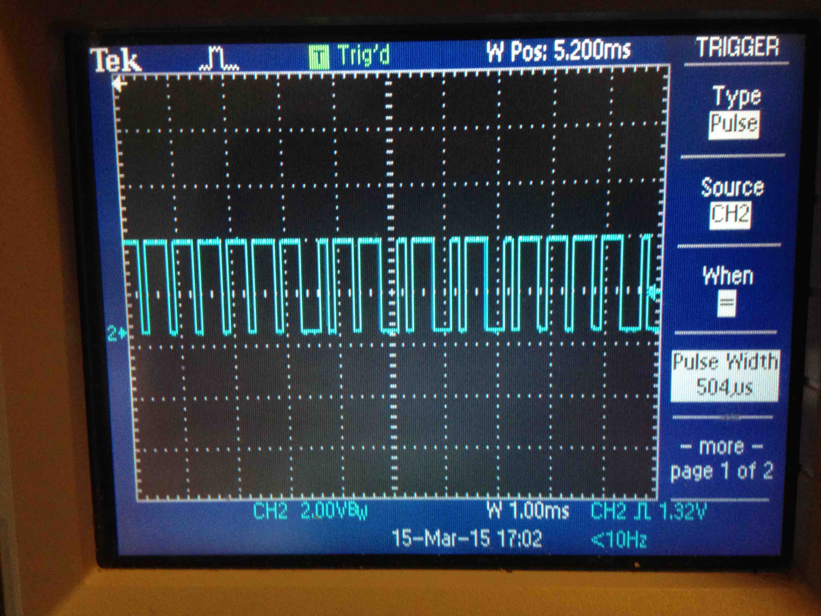
As far as the IDLE high or IDLE low state, looking at the signal with a scope, where is the bus signal level when NO data is being sent? I would imagine it to be high, as most single wire communications use a passive sourced current to stimulate the bus wire (usually a resistor). That way there can be more than 1 device listening as well as more than 1 device able to answer a request. This is done by pulling the line LOW thru an open collector transistor or N channel fet.
Dave Purola,
N8NTA
EN82fn


Bookmarks