TABSoft,
As best I can tell, your concern for accuracy comes into play when the clock is allowed to count up to a (relatively) large number.
While doing some testing on seconds counts in the 5 year or greater range, I found that Henrik's routine took over a second to complete (@ 4 MHz osc speed) so I added this bit of code...
Code:
IF owDays >=365 THEN
        GOSUB calcOWtime
        GOSUB setOWtime
        owDays=0
    ENDIF
This way the 32 bit counter will not get to large (assuming the microcontroller is turned on at least every year or so. Then this next bit of code is executed. Which converts the HH:MM:SS back into a "seconds count" and programmed back into the RTC, thus clearing the upper portion of the 32 bit counter.
Code:
'= = = = = = = = = = = = = = = = = = = = = = = = = = = =
   ' Subroutine to calculate OW time bytes A,B,C,D
'= = = = = = = = = = = = = = = = = = = = = = = = = = = =
'this routine take the three values HH, MM, SS and converts them to a
' 32 bit seconds count and loads the 4 Bytes A,B,C,D
calcOWtime:
    AB= owHH ** 3600
    CD= owHH *  3600 + owMM*60 + owSS
    ByteA=AB.byte1
    ByteB=AB.byte0
    ByteC=CD.byte1
    ByteD=CD.byte0
return

'= = = = = = = = = = = = = = = = = = = = = = = = = = = =
         ' Subroutine to write OW time
'= = = = = = = = = = = = = = = = = = = = = = = = = = = =
setOWtime:
   OWOUT OWTPin,%011,[$CC,$99,%10001100,ByteD,ByteC,ByteB,ByteA] 'set OW clock %10001100 OSC on
return
I realize that this little routine might introduce a few milliseconds error once every year or so to reset the counter to <365 Days.
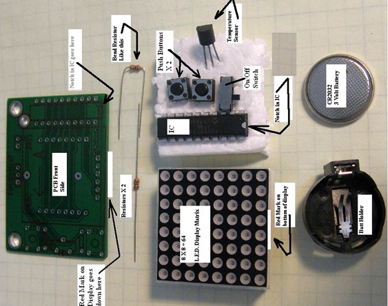
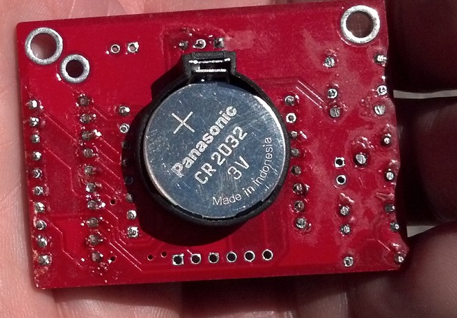
But, bear in mind that my project is a BOY SCOUT "Electronics" merit badge kit. The kit is powered by a CR2032 coin cell. It fills the final requirement to solder up a project.
Over the past 3-4 years we have built over 400 of these little kits.
I am just toying with the idea of allowing the kit to keep time.
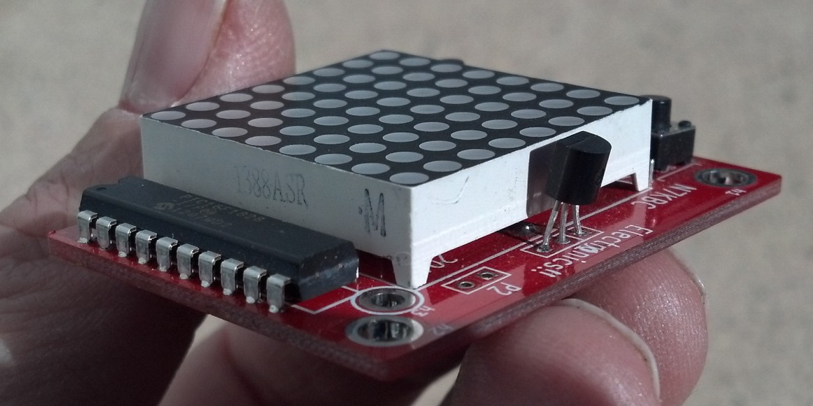
Currently here is what the kit does...
* displays the Boy Scout Law
* display current temperature
* track and remember Low and High temperature (if left on,
goes to sleep to save batt and wakes up every 60 sec to check temp)
* play a little race car game
* display several smiley faces and other icons
I designed this kit to be useful and teach microcontrollers
(which is what most hobby "electronics" today is centered around)
Since I have to re-order more PC boards I thought I would add an RTC to the design.
(I would pre solder the RTC and crystal as it is surface mount)
the Scouts do amazingly well for such small soldering. I have an experienced solder coach sit across from them as they build the kit in about 30 min.
What do you think...


Bookmarks