Sorry to keep beating on this post! I just really want to figure this out and having support is nice. Also, this is what I do on my lunch break ha-ha... So I write everthing in notepad, post it here and then I can cut and paste to my IDE when I get home 
Anyone care to look and maybe do a little bug hunting? I'm probably doing something wrong here. Something feels funny about having interrupts enable other interrupts. Maybe something will go wrong when those interrupts return? I'm not used to "Main" sitting there twirling away and then having my TMR0 doing it's own thing, which also happens to the be the starting point for all the real work.
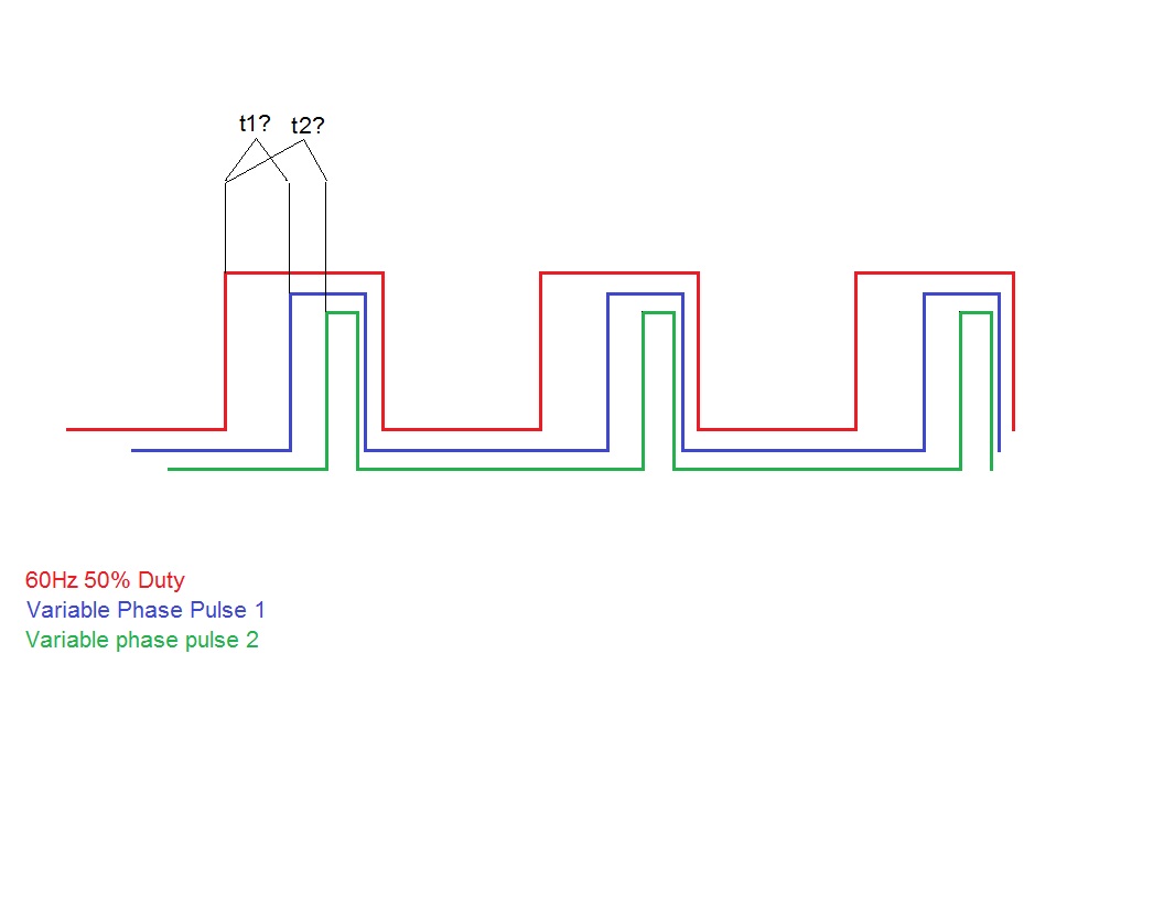
But what i think should happen is: each time the PulseGen ISR fires off a rising edge, it will start by intializing everything and then it will start TMR1 ticking and look to see which CCP interrupt was last enabled, and if the first one wasn't, it will enable it and mask it so it doesn't get selected the next go around. When CCP1 gets a rising edge, it will stop TMR1, disable itself and TMR1 interrupts, get the count from TMR1 into a variable and return (uh-oh...)
If all goes to plan, it will start over and do the same with CCP2 and unmask CCP1 for the next round.
My worries are since all this is happening from the TMR0 PulseGen interrupt, its timing will be at the mercy of those CCP and TMR1 interrupts... Also where those interrupts are getting returned to. Is that a safe place? Will it continue to skip out of the IF THEN ELSE traps and allow PulseGen to continue on? Maybe a GOTO PulseGen: added to the return points???
Interrupts are hard on the brain! 
Thanks again!!! I promise once I get this going as desired I will give a full disclosure as to what it's for - some of you might find a good use for it. Oh, and I'll shut up and go away for a while
Code:
INCLUDE "DT_INTS-18.bas"       		' Base Interrupt System
INCLUDE "ReEnterPBP-18.bas"     	' Include if using PBP interrupts

DEFINE OSC 20                           ' Running with a 20MHz x-tal
DEFINE HSER_BAUD 9600
DEFINE HSER_TXSTA 20h

@ __CONFIG    _CONFIG1H, _HS_OSC_1H & _FSCM_OFF_1H & _IESO_OFF_1H
@ __CONFIG    _CONFIG2L, _PWRT_OFF_2L & _BOR_OFF_2L
@ __CONFIG    _CONFIG2H, _WDT_OFF_2H & _WDTPS_1_2H
@ __CONFIG    _CONFIG4L, _STVR_OFF_4L & _LVP_OFF_4L & _DEBUG_OFF_4L
@ __CONFIG    _CONFIG3H, _CCP2MX_OFF_3H & _PBAD_DIG_3H & _MCLRE_OFF_3H

ADCON1 = 7				' Turn off analog inputs
TRISB = %11110111                   	' Set PortB direction.
T0CON = %10000001                  	' TMR0 16 bit Prescaler 1:4 ratio
T1CON = %00000000			' TMR1 prescale 1:1 clock=Fosc/4, TMR1=off (200nS per count @20MHz)
CCP1CON = %00000101  			' CCP1 Capture mode, capture on rising edge
CCP2CON = %00000101  			' CCP2 Capture mode, capture on rising edge

TrigOut    VAR PortB.3                  ' Pin for 60Hz output
OverFlows  VAR BYTE 			' Timer1 overflow total
Remainder1  VAR WORD 			' Remaining Timer1 ticks after first pulse capture
Remainder2  VAR WORD 			' Remaining Timer1 ticks after second pulse capture
FirstCapt  VAR BIT : FirstCapt = 0
PreLoad    VAR WORD : PreLoad = 52000   ' Preload TMR0 for 120Hz interrupt rate


;----[High Priority Interrupts]-------------------------------------------------------------------

ASM
INT_LIST  macro    ; IntSource,        Label,  Type, ResetFlag?
        INT_Handler    TMR0_INT,  _PulseGen, PBP,  yes
        INT_Handler    TMR1_INT,  _Timer1,   PBP,  yes
        INT_Handler    CCP1_INT,  _Capture1, PBP,  yes
        INT_Handler    CCP2_INT,  _Capture2, PBP,  yes
    endm
    INT_CREATE                          ' Creates the interrupt processor
ENDASM

@ INT_ENABLE TMR0_INT          		' Enable the 120Hz interrupt for the square wave generator.

'-------------------------------------------------------------------------------------------------

'---[Main Routine]--------------------------------------------------------------------------------

Main:
     IF T1CON.0 = 0 THEN 		' If TMR1 done, show result
	HSEROUT["Timer Overflows = ",DEC OverFlows,"Ticks 1 = ",DEC Remainder1,"Ticks 2 = ",DEC Remainder2,10,13]
     ENDIF
GOTO Main:

'-------------------------------------------------------------------------------------------------

'---[TMR0 - Interrupt handler / 60Hz Squarewave Trigger Pulse Generator]--------------------------

PulseGen:
   IF TrigOut = 0 THEN			' If trig output is low....
     TrigOut = 1                        ' Set trig output high
     TMR1L = 0                     	' Clear Timer1 Low Byte count
     TMR1H = 0     			' Clear Timer1 High Byte counts
     T1CON.0 = 1                   	' Turn Timer1 on at rising edge capture
     OverFlows = 0                 	' Clear over flow counts
     Remainder = 0                 	' Clear remainder
     PIR1.0 = 0                    	' Clear Timer1 overflow flag before enable
@    INT_ENABLE  TMR1_INT         	' Enable Timer 1 Interrupts
     IF FirstCapt = 0 THEN              ' If first pulse hasn't been looked for yet...
        FirstCapt = 1                   ' Mark it as such and...
@    INT_ENABLE  CCP1_INT               ' Start looking for 1st pulse
     ELSE
     FirstCapt = 0                      ' Reset first pulse search mask and...
@    INT_ENABLE  CCP2_INT               ' Start looking for 2st pulse
     ENDIF
ELSE
     TrigOut = 0                        ' Trig output was high, set it low.
ENDIF

TMR0L = PreLoad.LowByte       		' TMR0 High and low bytes preloaded
TMR0H = PreLoad.HighByte
@ INT_RETURN

'-------------------------------------------------------------------------------------------------

'---[CCP1 - interrupt handler]--------------------------------------------------------------------

Capture1:
     T1CON.0 = 0                   	' Stop Timer1
@    INT_DISABLE  TMR1_INT    		' Disable Timer 1 Interrupts
@    INT_DISABLE  CCP1_INT    		' Disable CCP1 Interrupts
     Remainder1.LowByte = TMR1L    	' Get remaining Timer1 counts
     Remainder1.HighByte = TMR1H
@ INT_RETURN

'-------------------------------------------------------------------------------------------------

'---[CCP2 - interrupt handler]--------------------------------------------------------------------

Capture2:
     T1CON.0 = 0                   	' Stop Timer1
@    INT_DISABLE  TMR1_INT    	   	' Disable Timer 1 Interrupts
@    INT_DISABLE  CCP2_INT         	' Disable CCP2 Interrupts
     Remainder2.LowByte = TMR1L    	' Get remaining Timer1
     Remainder2.HighByte = TMR1H
@ INT_RETURN

'-------------------------------------------------------------------------------------------------

'---[TMR1 - interrupt handler]--------------------------------------------------------------------
Timer1:
    OverFlows = OverFlows + 1      	' Count the number of times TMR1 overflows
@ INT_RETURN

'-------------------------------------------------------------------------------------------------

GOTO Main:

END


Bookmarks