


Hello all,
Long time, no post. Hope everyone is well. I'm sure hoping one of you brilliant minds can assist or critique an analog circuit I'm working on.
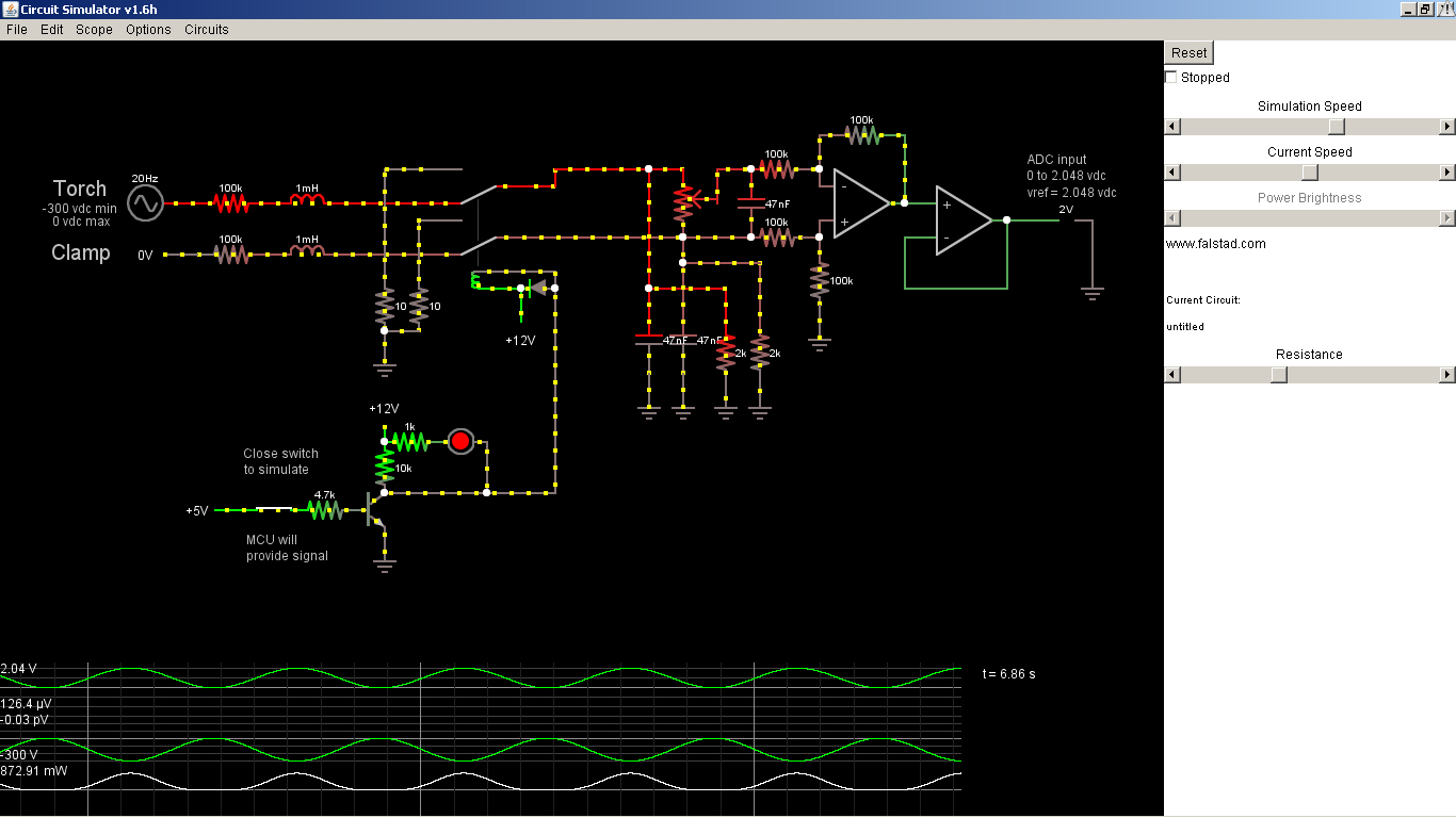
This circuit will scale the NEGATIVE dc voltage (ground referenced) of my plasma cutter, down to a usable ADC level. I've been simulating it
with the Falstad circuit simulator and it seems to work, but I would much rather have a second, third, fourth, etc. opinion on it. If you would like,
I can post the Falstad file in a code block as well.
Thank you all for your continued help in my crazy projects,
Chris


 All of the other THC's out there do it with a scaler (divider)... Oh boy, I'm baffled now!
 I do have to admit, it is self-serving too. Heck, I'll get a THC out of it too. Here's some progress of the PCB's ready to go to OSHPark. RS232 and 20x4 lcd display through the RJ-45 jacks up top. All menus and settings will be controlled through a 24 detent encoder with a built-in push switch. The scaler and gpio boards are set up as daughter boards to the main board as well. I guess I should breadboard the project, now that I have the PCB's done


Bookmarks