


Hi everyone;
I'm upto a triac control circuit . So , in order to control the triac triggering angle we need to detect the zero crossing points .. I've made the attached circuit schematic on a breadboard but I'm having too weird problem about the full wave rectified sine wave .. The rectified wave can not reach to zero cross twice but only once during a period and plots an unintended line as seen on the attached picture .. I've changed the circuit components for a thousands of times including the resistors , capacitors , bridge rectifiers , transistors even the breadboard ... The rectified wave even acts same on a single load resistor ...
What could the problem be ?
PLEASE HELP ...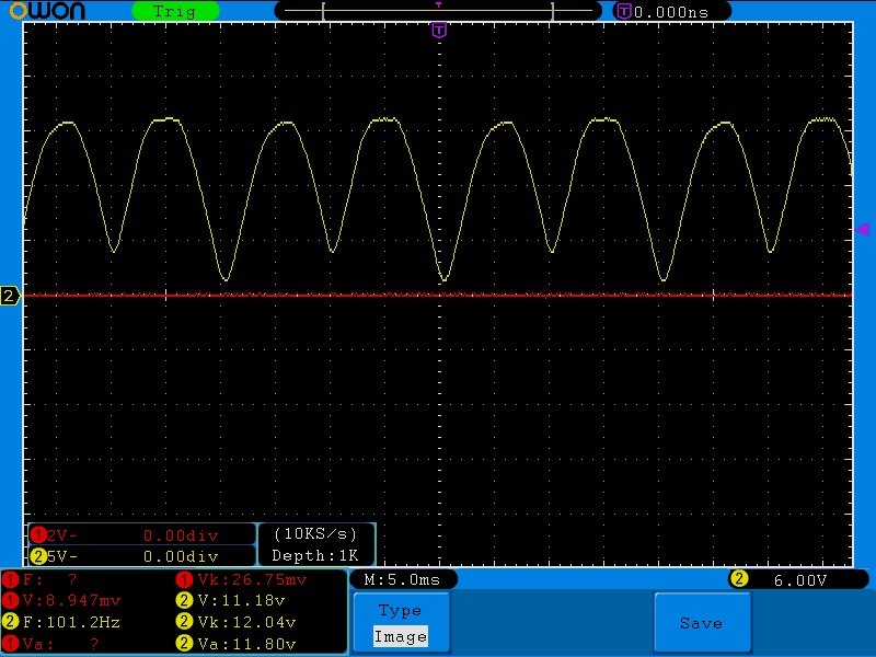


Bookmarks