parameters on which PIC is selected


Closed Thread
Results 1 to 14 of 14

Hybrid View

  1. #1
    Join Date
    Mar 2014
    Posts
    7


    Did you find this post helpful? Yes | No

    Default Re: parameters on which PIC is selected

    hey thanks man
    bt the prob is der r gating signals with varying duty cycles evrytim the carrier cuts with the reference signal so how its possible to measure the duty cycle of the signals ,to program accordingly .m attaching snapshot of the matlab simulation result.
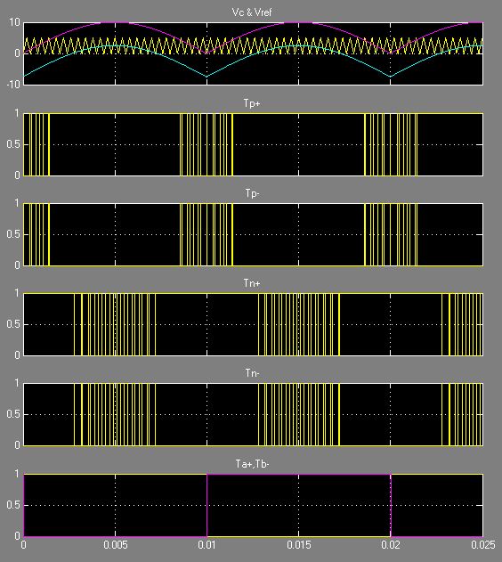
Name:  gating signals.JPG
Views: 537
Size:  72.9 KB

  2. #2
    Join Date
    Oct 2005
    Location
    Sweden
    Posts
    3,612


    Did you find this post helpful? Yes | No

    Default Re: parameters on which PIC is selected

    Hi,
    I'm sorry, I have no idea.

  3. #3
    Join Date
    Apr 2014
    Location
    OK
    Posts
    557


    Did you find this post helpful? Yes | No

    Default Re: parameters on which PIC is selected

    May I suggest the PIC16F1824 (14-pin) or PIC16F1828 (20-pin) enhanced processors. Get the data sheet, these chips are awesome for what you're wanting to do! First, they include 4 ECCP channels, allow you to invert outputs, PLUS include a cool feature called Data Signal Modulator (DSM) that would allow you to embed your higher frequency within the slow clock, and even PWM that higher frequency while PWM the slow clock.

    Hope this helps.
    Mike

  4. #4
    Join Date
    Mar 2014
    Posts
    7


    Did you find this post helpful? Yes | No

    Default Re: parameters on which PIC is selected

    hey thanks man
    bt the prob is der r gating signals with varying duty cycles evrytim the carrier cuts with the reference signal so how its possible to measure the duty cycle of the signals ,to program accordingly,hardware point of view .m attaching snapshot of the matlab simulation result.Name:  gating signals.JPG
Views: 513
Size:  72.9 KB

  5. #5
    Join Date
    Apr 2014
    Location
    OK
    Posts
    557


    Did you find this post helpful? Yes | No

    Default Re: parameters on which PIC is selected

    If you have a fixed period (as shown in the above pic), then measure either on-time or off-time with T1G (or T2G, T3G, etc) and subtract it from the total period. Simple math & you have your DC%.

    If you have a varying period, use "Toggle Mode" to measure a period, then disable Toggle Mode and set up Single-Shot Mode to measure either on or off time. From there it is once again simple math.

    Am I getting closer?

    Mike

  6. #6
    Join Date
    May 2013
    Location
    australia
    Posts
    2,653


    Did you find this post helpful? Yes | No

    Default Re: parameters on which PIC is selected

    try this

    move1:
    Lbyte = (position1 & %00001111) 'servo 0 + lownib
    Hbyte = %10000000 |( (position1 & %11110000)>>4) 'servo 0 + highnib
    SEROUT2 serial_out,baud1,[Lbyte,Hbyte] 'send command to FT639
    PAUSE 100
    RETURN

    edit oops wrong thread
    Last edited by richard; - 6th April 2014 at 00:48.

  7. #7
    Join Date
    Mar 2014
    Posts
    7


    Did you find this post helpful? Yes | No

    Default Re: parameters on which PIC is selected

    hi mike
    gt ur point,so ur saying taking the reference and carrier signal (20khz) frm ADC n checking for its on and off time??
    cos if you c ma reference its a absolute and i dnt have my negative cycle.so how do i generate my ref n carrier 1st??
    i'am thinking of taking in signals from ADC and den comparing...
    m i right??

  8. #8
    Join Date
    Mar 2014
    Posts
    7


    Did you find this post helpful? Yes | No

    Default Re: parameters on which PIC is selected

    CCPxM3:CCPxM0 (CCPxCON<3:0>) to capture every rising edge of the waveform ??if m considering 18f4431 ...

  9. #9
    Join Date
    Apr 2014
    Location
    OK
    Posts
    557


    Did you find this post helpful? Yes | No

    Default Re: parameters on which PIC is selected

    The DSM feature would allow you to select a comparator as one of your qualifiers. Whenever your arcing input exceeds your selected (possibly through DAC) threshold, your HF is passed through. FWIW I played with the PIC16F1828 this weekend specifically to experiment with the DSM.

    Here's what my version looked like:

    http://s223.photobucket.com/user/mpgchris/media/246_zps91083c15.jpg.html

    Mike

Similar Threads

  1. Serin parameters ??
    By Rony in forum General
    Replies: 6
    Last Post: - 21st August 2011, 18:01
  2. dc motor parameters
    By iugmoh in forum Off Topic
    Replies: 0
    Last Post: - 10th October 2009, 19:32
  3. DC motor parameters ?
    By iugmoh in forum Off Topic
    Replies: 2
    Last Post: - 28th June 2008, 10:46
  4. MCSP Bootloader Parameters
    By CocaColaKid in forum General
    Replies: 0
    Last Post: - 19th September 2005, 18:15
  5. @ Device Parameters
    By Randy_Suwanee in forum General
    Replies: 2
    Last Post: - 11th August 2004, 14:40

Members who have read this thread : 0

You do not have permission to view the list of names.

Tags for this Thread

Posting Permissions

  • You may not post new threads
  • You may not post replies
  • You may not post attachments
  • You may not edit your posts