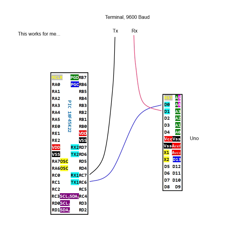
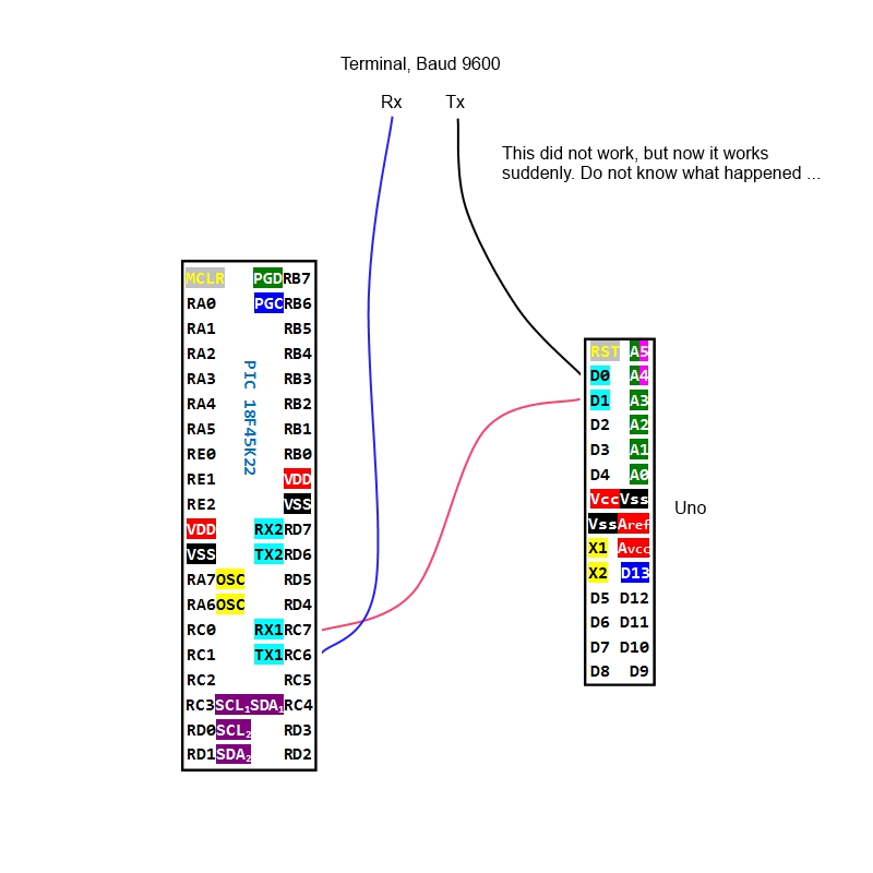
Hi All
All right. Thanks for the response.
It's a bit embarrassing and I'm pretty confused for a sudden does it all as it should without I know what caused it. It's very simple setup but for several days it has teased me.
Test set-up:


Here's the test code I'm using:
18F45K22:
Code:
#CONFIG
    CONFIG  FOSC = INTIO67        ; Internal oscillator block
    CONFIG  PLLCFG = ON           ;
    CONFIG  PRICLKEN = OFF        ; Primary clock can be disabled by software
    CONFIG  FCMEN = OFF           ; Fail-Safe Clock Monitor disabled
    CONFIG  IESO = OFF            ; Oscillator Switchover mode disabled
    CONFIG  PWRTEN = OFF          ; Power up timer disabled
    CONFIG  BOREN = SBORDIS       ; Brown-out Reset enabled in hardware only (SBOREN is disabled)
    CONFIG  BORV = 190            ; VBOR set to 1.90 V nominal
    CONFIG  WDTEN = ON            ; WDT is always enabled. SWDTEN bit has no effect
    CONFIG  WDTPS = 32768         ; 1:32768
    CONFIG  CCP2MX = PORTC1       ; CCP2 input/output is multiplexed with RC1
    CONFIG  PBADEN = OFF          ; PORTB<5:0> pins are configured as digital I/O on Reset
    CONFIG  CCP3MX = PORTB5       ; P3A/CCP3 input/output is multiplexed with RB5
    CONFIG  HFOFST = ON           ; HFINTOSC output and ready status are not delayed by the oscillator stable status
    CONFIG  T3CMX = PORTC0        ; T3CKI is on RC0
    CONFIG  P2BMX = PORTD2        ; P2B is on RD2
    CONFIG  MCLRE = EXTMCLR       ; MCLR pin enabled, RE3 input pin disabled
    CONFIG  STVREN = ON           ; Stack full/underflow will cause Reset
    CONFIG  LVP = OFF             ; Single-Supply ICSP disabled
    CONFIG  XINST = OFF           ; Instruction set extension and Indexed Addressing mode disabled (Legacy mode)
    CONFIG  DEBUG = OFF           ; Disabled
    CONFIG  CP0 = OFF             ; Block 0 (000800-001FFFh) not code-protected
    CONFIG  CP1 = OFF             ; Block 1 (002000-003FFFh) not code-protected
    CONFIG  CP2 = OFF             ; Block 2 (004000-005FFFh) not code-protected
    CONFIG  CP3 = OFF             ; Block 3 (006000-007FFFh) not code-protected
    CONFIG  CPB = OFF             ; Boot block (000000-0007FFh) not code-protected
    CONFIG  CPD = OFF             ; Data EEPROM not code-protected
    CONFIG  WRT0 = OFF            ; Block 0 (000800-001FFFh) not write-protected
    CONFIG  WRT1 = OFF            ; Block 1 (002000-003FFFh) not write-protected
    CONFIG  WRT2 = OFF            ; Block 2 (004000-005FFFh) not write-protected
    CONFIG  WRT3 = OFF            ; Block 3 (006000-007FFFh) not write-protected
    CONFIG  WRTC = OFF            ; Configuration registers (300000-3000FFh) not write-protected
    CONFIG  WRTB = OFF            ; Boot Block (000000-0007FFh) not write-protected
    CONFIG  WRTD = OFF            ; Data EEPROM not write-protected
    CONFIG  EBTR0 = OFF           ; Block 0 (000800-001FFFh) not protected from table reads executed in other blocks
    CONFIG  EBTR1 = OFF           ; Block 1 (002000-003FFFh) not protected from table reads executed in other blocks
    CONFIG  EBTR2 = OFF           ; Block 2 (004000-005FFFh) not protected from table reads executed in other blocks
    CONFIG  EBTR3 = OFF           ; Block 3 (006000-007FFFh) not protected from table reads executed in other blocks
    CONFIG  EBTRB = OFF           ; Boot Block (000000-0007FFh) not protected from table reads executed in other blocks
#ENDCONFIG


DEFINE OSC 64

' Setup PLL for 64 MHZ
OSCCON = 110100 ; 16 mhz (NOTE: SCS=0 so PLL works)
OSCTUNE.6 = 1 ;  PLL enable Mhz * 4

ANSELA = 0
ANSELB = 0
ANSELC = 0
ANSELD = 0
ANSELE = 0

' Set receive register to receiver enabled
DEFINE HSER_RCSTA    90h
' Set transmit register to transmitter enabled
DEFINE HSER_TXSTA    20h
' Set baud rate
DEFINE HSER_BAUD    9600
DEFINE HSER_CLROERR 1  ' Auto clear over-run errors

char Var byte  ' Storage for serial character

    Pause 2000

    Hserout ["PIC - UP RUNNING :-)", 13, 10] ' Send text followed by carriage return and linefeed

start:
       pause 10
       toggle PORTC.0  ' Alive LED

mainloop:
       Hserin 10000, start, [char]    ' Get a char from serial port
       pause 10
       Hserout [char]        ' Send char out serial port
       Goto mainloop        ' Do it all over again

End
Arduino Uno (only the chip - ATmega328p):
Code:
int led = 13;

int incomingByte = 0;   // for incoming serial data

void setup() {
  Serial.begin(9600);
  // initialize the digital pin as an output.
  pinMode(led, OUTPUT);
  Serial.println("Arduino UNO - UP RUNNING...");
}

// the loop routine runs over and over again forever:
void loop() {
  digitalWrite(led, HIGH);
  delay(100);
  digitalWrite(led, LOW);
  delay(900);

  if (Serial.available() > 0) {
    while (Serial.available()) {
      Serial.print((char)Serial.read());
    }
    Serial.println();
  }
}
Bookmarks