

Nice project
I never got chance to play with valves...


Nice project
I never got chance to play with valves...

Thanks
Some vintage amps don't even have a clunk switch, and you're supposed to just turn it on at the power point,
and this "was" one of those.
Also, Just about every serious problem will make the transformer heat up, which could be detected for auto switch off,
but that might be too late for something, so it would be better to directly monitor some voltages,
if that doesn't present clock noise to it once shielded.
Put some ferrite beads on pcb near connector on every pin except ground, also put toroid on wires. That should remove lot switching noise...
Thanks for your help, it's not introducing noise, but will follow our advice anyway.
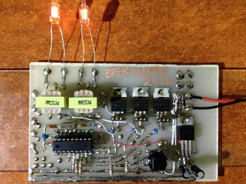
My first PCB that isn't just a tagstrip or something.
Perhaps something only I can love
I'm glad it works, and since it's the 60's, it's fine to hand draw it,
and use DIL ICs and components like they did in the 60's

Wow! What you reminded me... OK, I was not building anything in the 60's but later started with similar pcb's.
With today's way of thinking, this seems too much effort to light two neon bulbs, when you can do it with just a LED and a resistor.
Congrats, Art for your persistence and make it working!
Where did you find those retro transformers?
Ioannis
Hi, the transformers are new stock from my local electronics shop,
they have three types like this, and call them "transformers for decoupling",
and quote primary impedance, and nothing else. I was sure to grab spares.
One, I think was dodgy from the start, and should be replaced,
I can hear the PWM (even though very quiet) through one of the transformers.
I can even hear SOUND and DTMFOUT through that transformer.
It's not just for the neons.. I got the software relay switch working too so far:
It is possible to drive either side of a neon.
With either two transformers per channel,
or, I think, one transformer, and more MOSFETS,
you could move the light from side to side within one neon.
 Members who have read this thread : 0
You do not have permission to view the list of names.
 Posting Permissions


Bookmarks