Hello, thank you for visiting the picbasic users forum. Just a little note to remind you that, if your have registeted for a user account and you have not logged in and posted a message, unused accounts are deleted from time to time.
We track user account usage. As part of our general maintenaince and to meet the GDPR requirments, we have elected to delete user accounts that are unused.
We define unused as:
NOT haveing ever posted a message on the forum
AND
NOT having logged in for more than 360 days.
If you find that your account is deleted, because of inactivity, you will need to contact the forum administrator to have the account re-instated. email: [email protected]


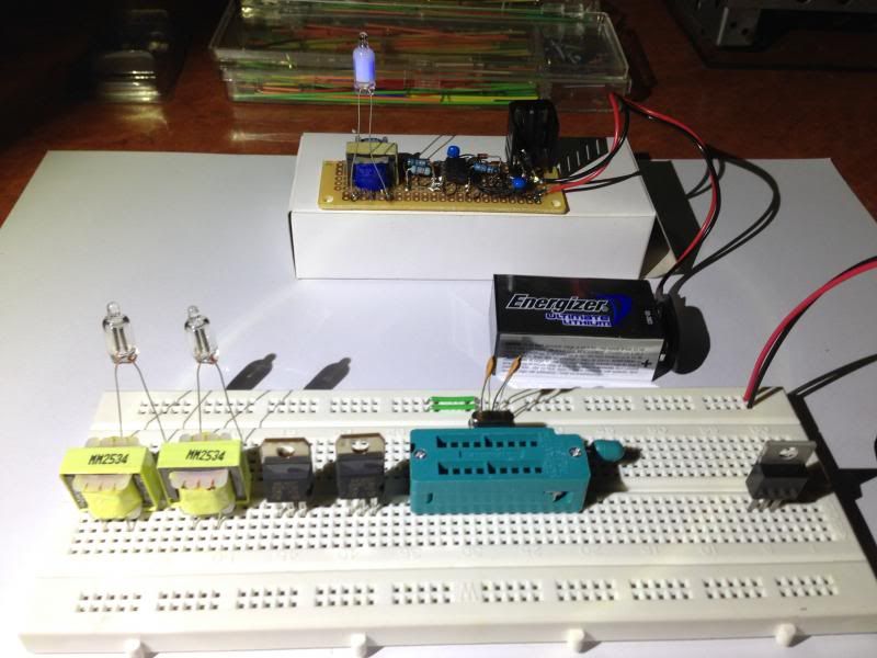


 No heat from anything, but I'm not sure the 1N004 protection
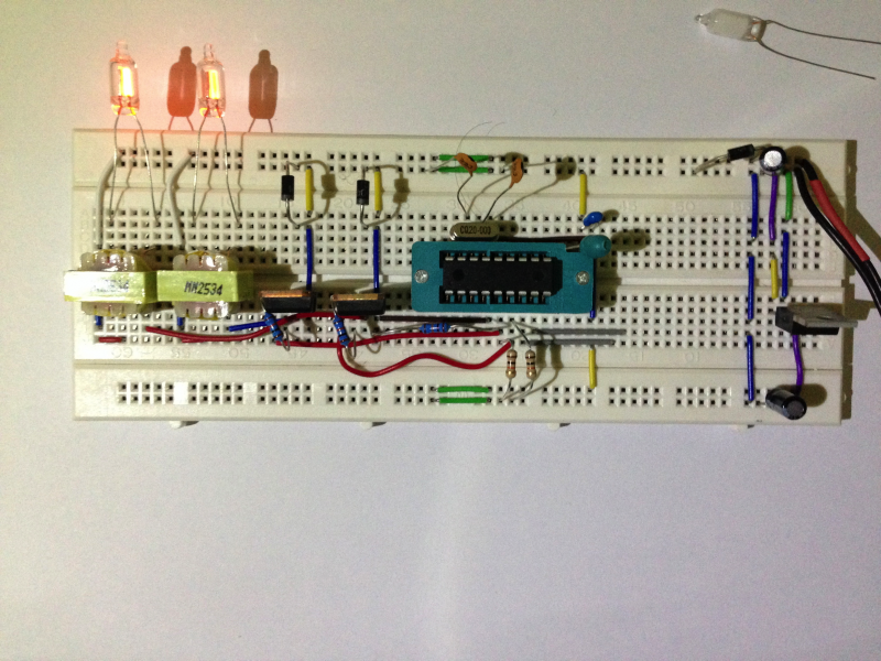


Bookmarks