


Hi Guys,
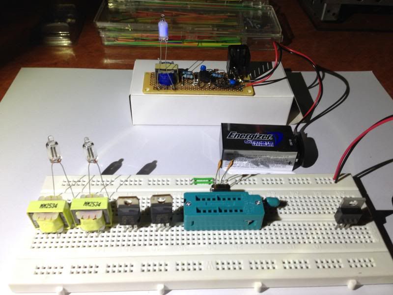
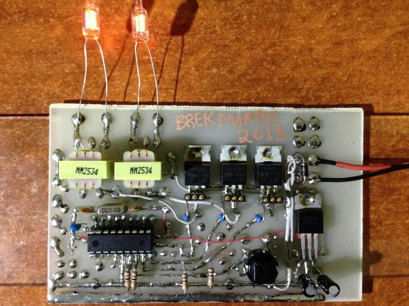
I did a circuit a while back... a schematic flogged off the net to drive a neon with low voltage.
It's 555 timer controlled, to pulse power to the transformer.
The MJE355 transistor gets very hot very quickly, and I never sorted that out.
THe transformer itself, stays cool.
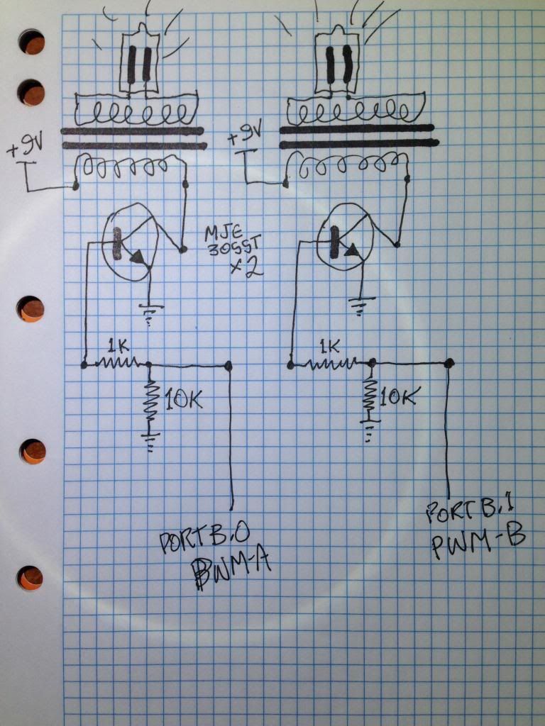
This time I can check the impedance of the transformer primary isn't real low,
and also I want to replace the 555 timer with a pic so I can vary the pulse width duty cycle and frequency.
Maybe some combination will cool it down.
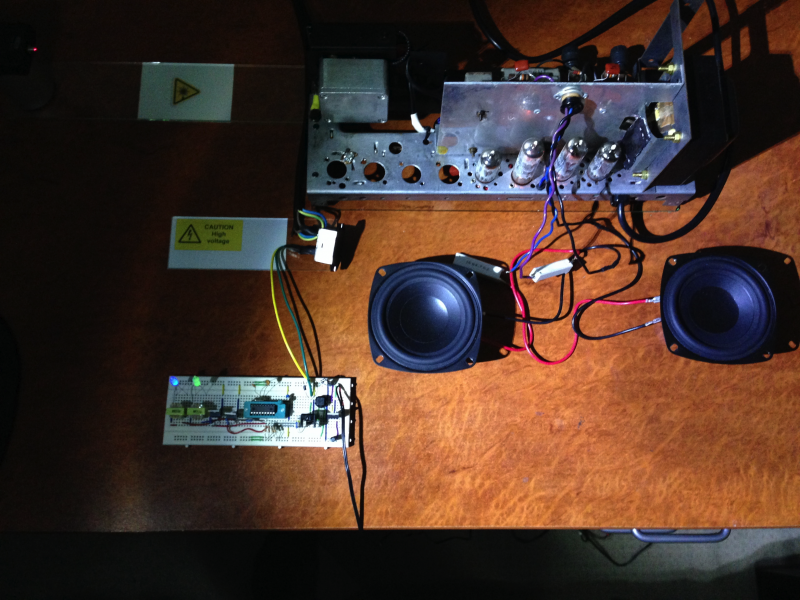
Also two channels, and the potential quick fix of dimming the neon on & off in steps rather
than leave it on constantly.
There will be some compromise on the dimming speed to ensure it can be cool.
Our local electronics supplier do blue, green , and original red neons now.


 No heat from anything, but I'm not sure the 1N004 protection
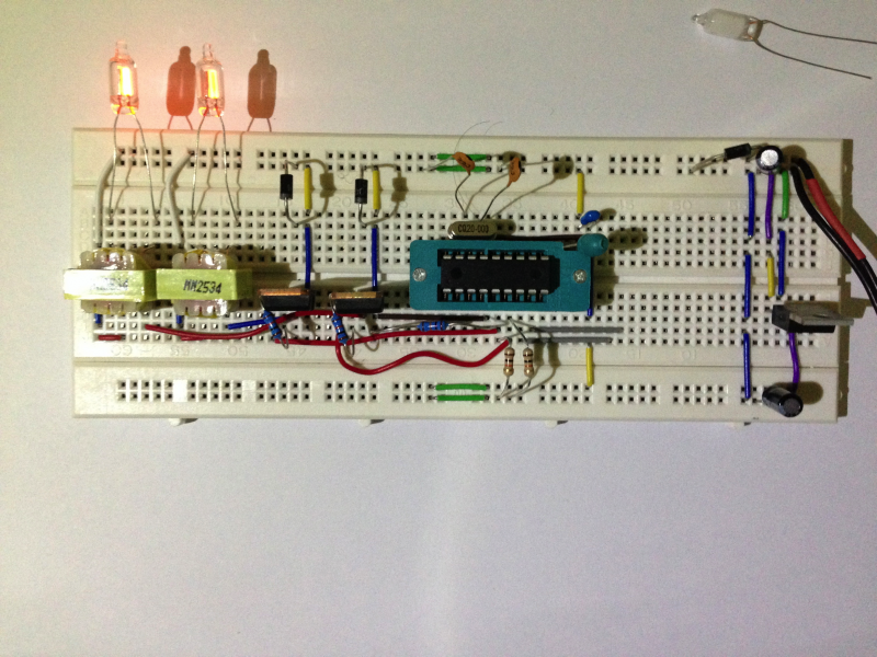


Bookmarks